Driving the ST7262 RGB Display on the ESP32-S3: LVGL Dashboard Full Tutorial (Waveshare Touch-LCD-5B / 1024×600)
Use ESP-IDF to bring up the RGB panel from scratch on the Waveshare ESP32-S3-Touch-LCD-5B (5-inch 1024×600, ST7262 pure-RGB direct-drive), hook up LVGL, and turn it into an animated vehicle telemetry dashboard. Covers CH422G backlight control, PCLK tuning, PSRAM double buffering and easing animations, with complete ESP-IDF code and a pitfall checklist.
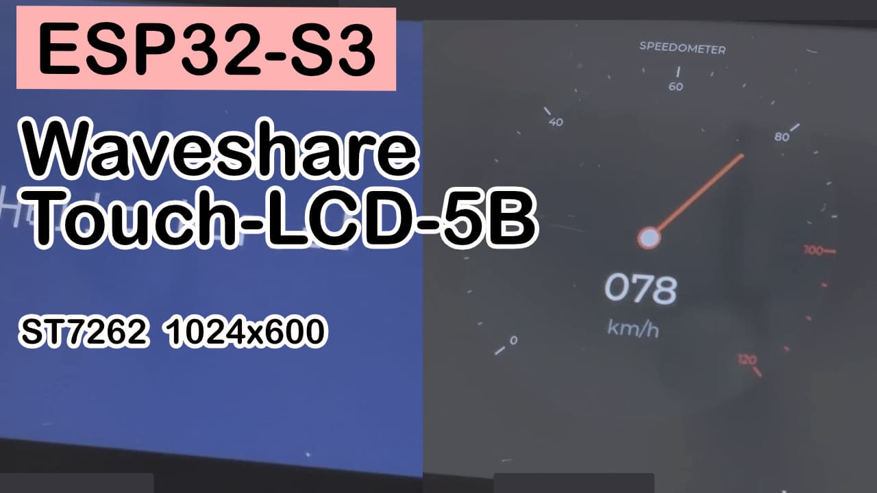
Difficulty: ⭐⭐⭐☆☆ (comfortable with basic C and some ESP-IDF exposure) Estimated time: 2–3 hours (including environment setup) Test environment: ESP-IDF 5.3.x (or 5.2.7 with one extra macro line) + LVGL ^9.3 + espressif/esp_lvgl_port 2.8
In one sentence: Use ESP-IDF on the Waveshare ESP32-S3-Touch-LCD-5B (5-inch 1024×600, ST7262 pure-RGB direct-drive) to bring an RGB panel from a black screen all the way up, hook up LVGL, and finally build an animated vehicle telemetry dashboard. Every pitfall I hit (the resolution trap, PCLK white screen, LVGL memory white screen, tearing and stutter) and the code that fills those holes lives here.
TL;DR (quick start):
- Know what you’re holding: the 5B is 1024×600, driven by ST7262, pure RGB direct-drive — don’t trust the 800×480 default in the official example.
- Use 16MHz for PCLK: don’t copy the 21MHz from the board definition; with a PSRAM framebuffer the bus can’t keep up and the screen goes pure white.
- Backlight goes through CH422G: it’s not a normal GPIO and not PWM — write a single byte to I²C address
0x38to switch it on/off.- Two macros are mandatory for LVGL:
LV_USE_CLIB_MALLOC=y+SPIRAM_USE_MALLOC=y, otherwise you get a white screen + watchdog reboot.idf.py build flash monitor, light it up, pop the champagne.
Preface
I was out of town this weekend, and a friend had bought a Waveshare ESP32-S3-Touch-LCD-5B. The official firmware could be flashed and would display fine, but he couldn’t get his own code to light it up — the official examples either stayed black or turned white, and he was completely stuck. So I took it off his hands and started wrestling with it. It’s a 5-inch, 1024×600 RGB capacitive touchscreen dev board. The board isn’t expensive, but the specs are surprisingly rich — CAN, RS485, RTC, LiPo charging, plus 16MB Flash + 8MB PSRAM on board.
So I picked it up to try to light it up — I’ve been on a real “lighting up displays” kick lately. But the process had more pitfalls than I expected. The most demoralizing part was: if you follow Waveshare’s official docs and examples, you can’t light it up. It’s not that you’re bad at this — it’s that the official resources simply aren’t prepared for this 5B variant.
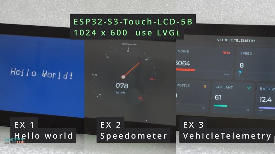
I split the whole process into three progressive little examples, all the code is on GitHub (this project’s full directory, all three examples are in there):
- Light up the screen: the most bare-bones approach, display a line of “Hello World” → 01 HelloWorld
- Hook up LVGL: build a semicircular speedometer with a needle animation → 02 Speedometer
- Turn it into a dashboard: evolve it into a designed vehicle telemetry panel → 03 VehicleTelemetry
Goal of this article: hand you the pitfalls from these three steps, the why behind the code that fills them, and a copy-paste-ready pitfall cheat sheet, so you can save yourself a few all-nighters.
Result
You’ll end up with an animated vehicle telemetry dashboard: five data cards for RPM, throttle, water temp, vehicle speed, and voltage, with values that ease toward their targets, progress bars that turn red on overload, and a needle that animates smoothly with no tearing.
1. Board overview: get to know this 5B first
Before the pitfalls begin in earnest, let’s lay out the hardware specs of the ESP32-S3-Touch-LCD-5B. The pitfalls that follow — what PCLK to fill in, whether memory is enough, which pins share an I²C bus — basically all revolve around this table, so it’ll be much smoother if you reference it as you read.
Display (this is what you should pin down first)
| Item | Spec |
|---|---|
| Size | 5 inch |
| Panel type | IPS |
| Resolution | 1024 × 600 (verified on hardware; the official docs don’t single out the 5B and default to 800×480 — this is the big trap of chapter 1) |
| Colors | 65K colors |
| Interface | RGB (parallel), driver IC ST7262, pure RGB direct-drive, no SPI init commands needed |
| Viewing angle | 175° |
| Brightness | 550 cd/m² |
| Touch | Capacitive touch (with glass cover) |
| Backlight boost chip | AP3032KTR-G1 |
ST7262 is an RGB-interface LCD panel driver IC (from Sitronix) that takes in parallel RGB signals and drives the liquid crystal. In this project you never have to send it any init commands — apply power, give it the right timings, feed it data, and it lights up on its own. That saves a lot of headache.
Main chip (MCU)
| Item | Spec |
|---|---|
| Module | ESP32-S3-WROOM-1-N16R8 |
| Core | Xtensa 32-bit LX7 dual-core, up to 240 MHz |
| Flash | 16 MB |
| PSRAM | 8 MB (octal SPI) |
| Internal SRAM | 512 KB |
| Wireless | Wi-Fi 2.4 GHz (802.11 b/g/n), Bluetooth 5 (LE), onboard antenna |
| USB | Full-Speed USB, onboard Type-C |
PSRAM is a “large but slow” memory chip sitting outside the main silicon. The full-screen framebuffer lives in this 8MB and is continuously shipped out to the panel by DMA. That 8MB PSRAM is where the full-screen image is stored. Misconfiguring PSRAM as quad is a common pitfall (see chapter 7).
Touch
| Item | Spec |
|---|---|
| Touch IC | GT911 |
| Type | Capacitive |
| Touch points | 5-point touch |
| Interface | I²C |
| I²C address | 0x5D |
GT911 is a capacitive touch controller that turns finger position into digital coordinates and reports them over I²C. In this project it shares the same I²C bus (GPIO8/GPIO9) with the RTC and CH422G, so addresses have to be planned out. This series of examples doesn’t drive the touch yet — that’s a follow-up TODO.
Power and interfaces
| Item | Spec |
|---|---|
| Power | Type-C 5V / DC 7–36V / single LiPo 3.7V (MX1.25) |
| Power draw | 5V / 450 mA (typical) |
| CAN | CAN 2.0 compatible (TJA1051, 120Ω terminator disabled by default) |
| RS485 | SP3485 transceiver (120Ω terminator disabled by default) |
| Operating temp | 0 °C ~ 65 °C |
| Dimensions | bare board 112.4 × 75.1 mm / with case 116.3 × 79 mm |
2. Onboard resource mapping (already on the dev board, no wiring needed)
⚠️ This is a dev board — the components are already soldered down. The tables below are onboard resource mappings, for checking pinouts and configuring the SDK, NOT for wiring things up with Dupont jumpers. All you have to do: plug in Type-C for power, plug USB into the computer to flash firmware.
RGB interface pinout for the display
The mapping below corresponds to the official documentation and has been verified against the actual hardware. Note that GPIO0 is a strapping pin (see the pitfall list in chapter 7).
| ESP32-S3 GPIO | LCD signal | Description |
|---|---|---|
| GPIO0 | G3 | Green data bit3 |
| GPIO1 | R3 | Red data bit3 |
| GPIO2 | R4 | Red data bit4 |
| GPIO3 | VSYNC | Vertical sync |
| GPIO4 | TP_IRQ | Touch interrupt |
| GPIO5 | DE | Data enable |
| GPIO7 | PCLK | Pixel clock (16MHz verified stable) |
| GPIO10 | B7 | Blue data bit7 |
| GPIO14 | B3 | Blue data bit3 |
| GPIO17 | B6 | Blue data bit6 |
| GPIO18 | B5 | Blue data bit5 |
| GPIO21 | G7 | Green data bit7 |
| GPIO38 | B4 | Blue data bit4 |
| GPIO39 | G2 | Green data bit2 |
| GPIO40 | R7 | Red data bit7 |
| GPIO41 | R6 | Red data bit6 |
| GPIO42 | R5 | Red data bit5 |
| GPIO45 | G4 | Green data bit4 |
| GPIO46 | HSYNC | Horizontal sync |
| GPIO47 | G6 | Green data bit6 |
| GPIO48 | G5 | Green data bit5 |
Touch / RTC / external I²C (shared bus)
| ESP32-S3 GPIO | Signal | Description |
|---|---|---|
| GPIO8 | SDA / TP_SDA / RTC_SDA | I²C data (shared by GT911 touch, PCF85063 RTC, external I²C) |
| GPIO9 | SCL / TP_SCL / RTC_SCL | I²C clock (shared, as above) |
| GPIO4 | TP_IRQ | Touch interrupt |
USB / SD / RS485 / CAN
| Function | ESP32-S3 GPIO | Description |
|---|---|---|
| USB D- / D+ | GPIO19 / GPIO20 | Full-Speed USB |
| SD MOSI / SCK / MISO | GPIO11 / GPIO12 / GPIO13 | SD card (SPI) |
| SD CS | (CH422G EXIO4) | Active-low, controlled by the IO expander, not on a native SPI CS |
| RS485 RXD / TXD | GPIO43 / GPIO44 | SP3485 |
| CAN TX / RX | GPIO15 / GPIO16 | TJA1051 |
A chip you can’t avoid: the CH422G IO expander
That chip on the board that the backlight and reset are all hanging off of is the CH422G, operated over I²C. Its quirk: it has no register pointer — the I²C device address itself is used as the command.
CH422G is an I²C IO expander that centrally manages the miscellaneous signals like backlight, display reset, touch reset, and SD card chip select. In this project you lean on it to switch on the backlight and reset the panel.
| CH422G pin | Function | Description |
|---|---|---|
| EXIO0 | DI0 | Digital input 0 |
| EXIO1 | TP_RST | Touch reset |
| EXIO2 | DISP | Backlight enable (on/off only, not dimmable) |
| EXIO3 | LCD_RST | Display reset |
| EXIO4 | SD_CS | SD card chip select (active-low) |
| EXIO5 | DI1 | Digital input 1 |
| OD0 | DO0 | Digital output 0 |
| OD1 | DO1 | Digital output 1 |
3. What you need to install: the ESP-IDF toolchain + components
This board doesn’t need a library installed, but it uses ESP-IDF (Espressif’s official development framework) rather than Arduino. Reason: the RGB-direct-drive + PSRAM framebuffer + LVGL combo has dozens of switches in sdkconfig (PCLK, PSRAM mode, memory pools), and those are far easier to control in ESP-IDF — tweaking them in Arduino is painful.
Checklist (work through it; it’ll save you 80% of debugging time):
- ESP-IDF 5.3.x (recommended). 5.2.7 also works but needs one extra macro line (see chapter 7).
- LVGL ^9.3 (
esp_lvgl_port2.8 depends on color constants newly added in 9.3). - espressif/esp_lvgl_port 2.8 (handles LVGL tick, dedicated task, locking for you).
- Windows users: use PowerShell + an EIM profile, don’t run
idf.pyinside Git Bash (it detectsMSYSTEMand refuses to work).
Component versions must be paired within the same generation: esp_lvgl_port 2.8 with LVGL ^9.3. Mismatch them and compilation throws RGB565_SWAPPED undeclared.
4. Step 1: light up the screen (don’t just copy the official example)
📦 Full code for this chapter: 01 HelloWorld — the most bare-bones approach, lighting up the screen and displaying a line of Hello World.
This is the biggest pitfall of the whole endeavor, and what I most want to talk about first.
Waveshare’s official ESP-IDF examples (like 08_lvgl_Porting) and documentation are basically all written for 800×480. Its #else default branch is 800×480. The official docs lump the entire 5-inch family into “800×480 or 1024×600” and specifically don’t call out what the 5B is.
If you flash the official example straight into the 5B without a second thought, you get a very confusing picture: the screen is mostly black with a white strip on the right (black + white). It’s not broken — it’s “feeding an 800×480 signal into a 1024×600 panel.” The panel is wider than the signal, so the extra pixels on the right have no signal and just display like that.
Add to that Waveshare’s naming convention where the “B” suffix often indicates a square panel (for example, the 4B is a 480×480 square), and I half-suspected the 5B was a 720×720 square that needed SPI init first. After a lot of wrestling I finally confirmed: the 5B is 1024×600, the driver IC is ST7262, it’s pure RGB direct-drive, and you don’t need to send any SPI init commands. That’s a big deal and saves a ton of work.
So the first step is always: don’t trust the resolution in the official example — confirm what your specific unit actually is.
The brute-force way to confirm is what we just did — feed it 800×480, see the white strip on the right, and infer it’s 1024×600 (only a panel wider than the signal would do that).
4.1 Boot sequence (the 6-step skeleton)
Once you understand its temperament, you can light it up. The boot sequence is really just 6 steps: bring up I²C → reset the panel via CH422G → build the RGB panel → draw the picture → turn on the backlight → CPU idles while DMA self-refreshes.
The “draw the picture and only then turn on the backlight at the very end” part is critical — it avoids that one ugly boot frame. In code, the order for lighting up is fixed:
/* Step 1: bring up the I²C bus first (GPIO8/9, shared with the GT911 touch and RTC). */
i2c_master_bus_handle_t i2c_bus = NULL;
i2c_master_bus_config_t bus_cfg = {
    .sda_io_num = 8, .scl_io_num = 9, .clk_source = I2C_CLK_SRC_DEFAULT,
    .flags.enable_internal_pullup = true,
};
i2c_new_master_bus(&bus_cfg, &i2c_bus);

/* Step 2: drive the CH422G — reset first, then release (backlight is still off here). */
ch422g_handle_t io = {0};
ch422g_init(&io, i2c_bus);
ch422g_set_outputs(&io, 0);                              /* All EXIO low: reset + backlight off */
vTaskDelay(pdMS_TO_TICKS(10));
ch422g_set_outputs(&io, CH422G_LCD_RST | CH422G_TP_RST); /* Release reset, backlight still off */
vTaskDelay(pdMS_TO_TICKS(120));                          /* Wait for the panel to come up */

/* Step 3: build the RGB panel, draw the picture into the PSRAM framebuffer (see next chunk) ... */

/* Step 4: picture is ready; only now turn on the backlight — pull EXIO2 high. */
ch422g_set_outputs(&io, CH422G_LCD_RST | CH422G_TP_RST | CH422G_BL);
Iron rule on ordering: the backlight always comes on last. During reset all EXIO are pulled low (backlight off), then after reset is released you draw the picture, and only once the picture is ready do you write EXIO2 high. Doing it the other way — backlight first, then draw — gets you an ugly boot frame.
4.2 How “write high to light up” works for the backlight: a minimal CH422G driver
“Write high to light up” for the backlight boils down to two things in code: write a CH422G driver, then call it in the right order during the boot sequence. The core of the driver is one thing — the address is the register: write the mode to 0x24, write one byte (which is the level of the 8 outputs) to 0x38. The minimal driver looks like this (full version in main/ch422g.c in the repo):
/* CH422G "register" = the I²C 7-bit device address itself (no separate register byte). */
#define CH422G_REG_MODE  0x24   /* Write 0x01 -> EXIO0..7 push-pull output */
#define CH422G_REG_OUT   0x38   /* Write one byte -> the level of EXIO0..7 */

/* EXIO output bits: bit n = level of EXIO_n (1 = high). */
#define CH422G_TP_RST   (1u << 1)   /* EXIO1 touch reset */
#define CH422G_BL       (1u << 2)   /* EXIO2 backlight enable */
#define CH422G_LCD_RST  (1u << 3)   /* EXIO3 display reset */

/* Create one I²C device handle for each of the two "address-is-register" slots. */
esp_err_t ch422g_init(ch422g_handle_t *ch, i2c_master_bus_handle_t bus) {
    i2c_device_config_t mode_cfg = { .device_address = CH422G_REG_MODE, .scl_speed_hz = 100000 };
    i2c_master_bus_add_device(bus, &mode_cfg, &ch->dev_mode);
    i2c_device_config_t out_cfg  = { .device_address = CH422G_REG_OUT,  .scl_speed_hz = 100000 };
    i2c_master_bus_add_device(bus, &out_cfg,  &ch->dev_out);

    uint8_t mode = 0x01;                              /* push-pull output mode */
    i2c_master_transmit(ch->dev_mode, &mode, 1, -1);
    uint8_t zero = 0;
    i2c_master_transmit(ch->dev_out,  &zero, 1, -1);  /* start with everything cleared */
    return ESP_OK;
}

/* One byte is the 8 output levels — this is "use the address as the command." */
esp_err_t ch422g_set_outputs(ch422g_handle_t *ch, uint8_t exio_mask) {
    return i2c_master_transmit(ch->dev_out, &exio_mask, 1, -1);
}
4.3 Building the RGB panel (the heart of this chapter)
This panel-building block is the heart of the whole chapter; the three pitfalls below will explain line by line why each value is filled in the way it is:
#define LCD_H_RES        1024
#define LCD_V_RES        600
#define LCD_PIXEL_CLK_HZ (16 * 1000 * 1000)   /* ← Pitfall 1: 16MHz, not the 21MHz from the board definition */

/* In RGB565 green is 6 bits (0..63), red/blue 5 bits (0..31); pure white is 31,63,31 (← Pitfall 2). */
#define RGB565(r, g, b)   ((((r) & 0x1F) << 11) | (((g) & 0x3F) << 5) | ((b) & 0x1F))
#define COLOR_BG          RGB565(2, 8, 20)     /* dark blue background */
#define COLOR_FG          RGB565(31, 63, 31)   /* true white */

esp_lcd_rgb_panel_config_t panel_cfg = {
    .data_width = 16,                          /* RGB565 = 16 bits */
    .bounce_buffer_size_px = 10 * LCD_H_RES,   /* SRAM bounce: prevents underrun white screen at 16MHz */
    .disp_gpio_num = -1,                       /* backlight is on CH422G, not a GPIO */
    .pclk_gpio_num  = 7, .vsync_gpio_num = 3, .hsync_gpio_num = 46, .de_gpio_num = 5,
    .data_gpio_nums = {
        14, 38, 18, 17, 10,        /* B3..B7 */
        39,  0, 45, 48, 47, 21,    /* G2..G7 */
         1,  2, 42, 41, 40,        /* R3..R7 */
    },
    .timings = {
        .pclk_hz = LCD_PIXEL_CLK_HZ,           /* ← Pitfall 1 */
        .h_res = LCD_H_RES, .v_res = LCD_V_RES,
        .hsync_pulse_width = 30, .hsync_back_porch = 40, .hsync_front_porch = 220,
        .vsync_pulse_width = 4,  .vsync_back_porch  = 8,  .vsync_front_porch = 4,
        .flags.pclk_active_neg = true,
    },
    .flags.fb_in_psram = true,                 /* full-screen ~1.17MB framebuffer goes in PSRAM */
};
esp_lcd_new_rgb_panel(&panel_cfg, &panel);
esp_lcd_panel_init(panel);                     /* ← Pitfall 3: add this line after building the panel */
Once the panel is built, you grab the framebuffer and can write pixels directly to it — ESP-IDF’s RGB panel doesn’t provide any drawing primitives beyond draw_bitmap, so the helloworld example ships its own lcd_fill / lcd_draw_text helpers (bitmap font, see lcd_draw.c in the repo):
/* Grab the PSRAM framebuffer and draw Hello World. */
void *fb = NULL;
esp_lcd_rgb_panel_get_frame_buffer(panel, 1, &fb);
lcd_draw_init((uint16_t *)fb, LCD_H_RES, LCD_V_RES);
lcd_fill(COLOR_BG);
lcd_draw_text((LCD_H_RES - tw) / 2, (LCD_V_RES - th) / 2, "Hello World!", 5, COLOR_FG);

/* Picture is ready; turn on the backlight last. After that, DMA refreshes the panel from PSRAM on its own, CPU idles. */
vTaskDelay(pdMS_TO_TICKS(60));
ch422g_set_outputs(&io, CH422G_LCD_RST | CH422G_TP_RST | CH422G_BL);
4.4 Three pitfalls that actually bit me
Pitfall 1: PCLK copied too high, whole screen goes white. When copying over the official Arduino board definition, the pixel clock (PCLK) was filled in as 21MHz, and the screen went pure white (not black). The truth: the picture lives in PSRAM and has to be continuously read out by DMA and shipped to the screen. 21MHz × 16 bits ≈ 336M bits per second of bandwidth, which is too much for the “PSRAM → DMA → screen” path. The moment it can’t keep up, the screen receives no valid sync signal and just displays a “no signal” white background. Drop it to 16MHz and it’s stable.
Pitfall 2: white text turned pink, almost went and re-ordered the pins. After lighting up, white text displayed as pink. My first reaction was that the green-channel pins were reversed — wrong. The real reason is that in RGB565 green is 6 bits (0–63), red and blue are only 5 bits (0–31). In RGB565(31, 31, 31), green’s 31 is barely half of 0–63; red and blue are full, green is half, so it mixes out to pink. Only RGB565(31, 63, 31) is true white. Color cast comes in two flavors: white becomes cyan = pin ordering problem; white becomes pink = wrong value filled in.
Pitfall 3: missing one line of init. The canonical flow is “build panel → reset → init → enable display,” but at first I only called the build-panel step. In most cases building it starts scanning automatically, but adding the line esp_lcd_panel_init() rules out the “DMA didn’t start” hazard — without it, the screen might be on sometimes and off others.
4.5 The single most valuable trick: look at how it’s not lighting up first
When facing “won’t light up,” the most useful trick is to first look at exactly how the screen isn’t lighting up:
- No backlight at all → it’s a CH422G / reset-sequence issue
- Backlight on but all white / all gray → RGB signal isn’t right (most common; check PCLK and timings)
- Backlight on but garbled / jittering → signal is there, timings are slightly off
- Backlight on but colors are wrong (white → cyan) → RGB channel order is reversed
Just that one observation splits the problem in half and saves a whole pile of wild guesses.
5. Step 2: hook up LVGL and animate a needle
📦 Full code for this chapter: 02 Speedometer — hook up LVGL and build a semicircular speedometer with a needle animation.
After lighting it up I wanted a moving interface, so I went with LVGL (a popular graphics library in the embedded world). The hookup uses the officially recommended espressif/esp_lvgl_port component, which takes care of LVGL’s tick, dedicated task, and locking for you, and pushes the rendered picture to the screen.
LVGL is an open-source embedded graphics library that draws UI elements like buttons, progress bars, and animations. In this project you lean on it to build the speedometer and dashboard, rather than hand-writing drawing code line by line.
The hookup itself isn’t long; the core is just building the RGB panel (in the speedometer example there’s one extra line, .num_fbs = 2, which is the double-framebuffer for tear prevention coming up below), then handing it to esp_lvgl_port:
const lvgl_port_cfg_t lvgl_cfg = ESP_LVGL_PORT_INIT_CONFIG();
lvgl_port_init(&lvgl_cfg);

const lvgl_port_display_cfg_t disp_cfg = {
    .panel_handle  = panel,
    .buffer_size   = LCD_H_RES * LCD_V_RES, /* Full screen: hard requirement of direct mode */
    .hres          = LCD_H_RES, .vres = LCD_V_RES,
    .color_format  = LV_COLOR_FORMAT_RGB565,
    .flags = {
        .direct_mode = true,   /* Draw straight into the panel framebuffer, skip one full-screen copy */
        .buff_dma    = false,
        .buff_spiram = true,   /* Drawing buffer in PSRAM (← Pitfall 1: SPIRAM_USE_MALLOC must be on first) */
        .swap_bytes  = false,  /* Parallel RGB panel, no byte-order swap */
    },
};
const lvgl_port_display_rgb_cfg_t rgb_cfg = {
    .flags = {
        .bb_mode       = true,  /* Using a bounce buffer → sync via on_bounce_frame_finish */
        .avoid_tearing = true,  /* Swap fb on frame boundary → prevents tearing (see end of this chapter) */
    },
};
lvgl_port_add_disp_rgb(&disp_cfg, &rgb_cfg);

/* Any lv_* call must acquire this lock first, to avoid colliding with esp_lvgl_port's render task. */
lvgl_port_lock(0);
dashboard_create();   /* build the speedometer + start the needle animation */
lvgl_port_unlock();
The three flags are the essence of this block: direct_mode lets LVGL draw straight into the panel framebuffer (saves one full-screen copy); avoid_tearing swaps the two framebuffers at the frame boundary (prevents tearing); buff_spiram moves the drawing buffer into PSRAM — this one looks harmless but is exactly what leads into the biggest pitfall below.
5.1 Pitfall 1 (the sneakiest): white screen + watchdog reboot
Once connected and flashed, the screen goes black for two seconds, then all white, and stops responding. That symptom is identical to the PCLK-too-high white screen from before, and I almost dove back into tuning timings.
Good thing this time I opened the serial monitor and looked at the boot log first. I immediately spotted the key line:
E task_wdt: CPU 0: taskLVGLThe LVGL task triggered the watchdog and got flagged as stuck by the system. This is software hanging, not a signal problem. Tracing the call stack revealed that the first time LVGL renders a full screen it has to temporarily allocate an MB-scale drawing buffer, but LVGL by default uses its own tiny internal pool of only 64KB — 1MB doesn’t fit in 64KB, so it churns back and forth, can’t finish rendering, the task hangs, and the watchdog blows up.
Interestingly, I had explicitly put the display buffer in PSRAM, so how could it still say there wasn’t enough memory? Because the display buffer (for “pushing pixels to the screen”) and the pool LVGL uses internally for drawing (for “computing the picture”) are two different things — don’t conflate them. The fix is just two switches:
CONFIG_LV_USE_CLIB_MALLOC=y    # LVGL uses the system malloc instead of the 64KB internal pool
CONFIG_SPIRAM_USE_MALLOC=y     # Lets the system malloc grab large blocks from PSRAM
There’s a more critical insight here: “white screen” alone has at least two completely different causes. One is an RGB signal/bandwidth issue (the PCLK one earlier); the other is software hanging that never gets to draw (this one). Always check the serial log first to tell them apart — don’t just start tuning timings the moment you see a white screen.
5.2 Pitfalls 2 & 3: component versions and IDF macros out of sync
- Pitfall 2 (component versions must be paired):
esp_lvgl_port2.8 internally uses color constants that LVGL 9.3 only just added. Pinning LVGL to~9.2will throwRGB565_SWAPPED undeclared; changing it to^9.3fixes it. - Pitfall 3 (IDF macro out of sync): the new
esp_lvgl_portchecks the macroSOC_LCDCAM_RGB_LCD_SUPPORTED, but it was only renamed in IDF 5.3 — in 5.2.7 it’s still the old name, and at runtime you get “This target does not support RGB”. The fix is to addadd_compile_definitions(SOC_LCDCAM_RGB_LCD_SUPPORTED=1)beforeproject()in the top-level CMakeLists.
5.3 “Not smooth” and “screen tearing” are both unrelated to compute speed
Once the speedometer was running, two new problems showed up: the needle moves not smoothly enough, and there’s tearing (a misaligned horizontal line across the middle of the picture). Neither has anything to do with how fast you compute.
First, the not-smooth part. I first worked out the panel’s physical refresh rate: 16MHz PCLK ÷ total pixels per frame ≈ 20Hz. In other words, this panel can only redraw the picture at most 20 times per second — no matter how fast the software is, that’s a hard ceiling. So “smooth or not” isn’t a frame-rate problem, it’s an animation curve problem. A needle that sweeps at constant speed and reverses instantly feels especially stiff; switch to ease-in-out (decelerate at both ends, accelerate in the middle) and the turnaround becomes natural.
/* 270° speedometer: ROUND_INNER mode, starts at 135°, leaves a 90° gap at the bottom. */
lv_obj_t *scale = lv_scale_create(scr);
lv_obj_set_size(scale, 460, 460);
lv_scale_set_mode(scale, LV_SCALE_MODE_ROUND_INNER);
lv_scale_set_range(scale, 0, 120);
lv_scale_set_angle_range(scale, 270);
lv_scale_set_rotation(scale, 135);          /* start angle, decides which way the gap faces */
lv_scale_set_total_tick_count(scale, 25);   /* one tick per 5 km/h */
lv_scale_set_major_tick_every(scale, 4);    /* a major tick every 4 minor ticks → 0,20,...,120 */

/* Called every animation frame: point the needle at v. The numeric readout refreshes only when the integer changes. */
static void gauge_set_value(void *var, int32_t v) {
    gauge_ctx_t *g = (gauge_ctx_t *)var;
    lv_scale_set_line_needle_value(g->scale, g->needle, 150, v);  /* needle, 150px long */
    int vi = (int)v;
    if (vi != g->last_int) {                 /* if the integer didn't change, don't touch the label — skip a redraw */
        g->last_int = vi;
        lv_snprintf(s_value_buf, sizeof(s_value_buf), "%03d", vi);
        lv_label_set_text(g->value_label, s_value_buf);
    }
}

/* 0 → 120 → 0, infinite loop. Smoothness hinges entirely on the last line. */
lv_anim_t a;
lv_anim_init(&a);
lv_anim_set_var(&a, &s_ctx);
lv_anim_set_exec_cb(&a, gauge_set_value);
lv_anim_set_values(&a, 0, 120);
lv_anim_set_duration(&a, 2500);                       /* 2.5s one way */
lv_anim_set_playback_duration(&a, 2500);              /* return trip: 0→120→0 */
lv_anim_set_path_cb(&a, lv_anim_path_ease_in_out);    /* ← decelerate at the ends, so the turnaround isn't stiff */
lv_anim_set_repeat_count(&a, LV_ANIM_REPEAT_INFINITE);
lv_anim_start(&a);
The key is the line lv_anim_set_path_cb(&a, lv_anim_path_ease_in_out). playback_duration makes the animation automatically bounce back from 120 to 0; at the bounce point the velocity would otherwise snap hard in reverse. ease-in-out makes it decelerate to 0 first and then accelerate in the new direction, so the eye barely catches the turn.
Now tearing. The cause is having only one picture buffer prepared; DMA is shipping it out continuously while LVGL writes a new one into it at the same time, with no synchronization, so a “half-new, half-old” frame gets pushed out. The fix is double buffering + vsync swap: two pictures, and DMA only ever ships out the complete one. Note: on this panel we must keep a small buffer called the bounce buffer (to prevent underrun white screen at 16MHz), so it’s “double framebuffer + bounce together” — you can’t just turn off the bounce like the official example does.
On this panel, “smooth” comes from the easing curve, “no tearing” comes from double buffering — both are unrelated to compute speed.
6. Step 3: turn it into a vehicle telemetry dashboard
📦 Full code for this chapter: 03 VehicleTelemetry — evolve it into a designed five-card vehicle telemetry panel.
Finally I swapped the speedometer for a proper-looking vehicle telemetry panel: five metrics — RPM, throttle, water temp, vehicle speed, voltage — each card with a big number, progress bar, and min/max scale, and the value turns red on overload. The data is randomly simulated, but the motion has to feel natural.
6.1 How a card is built
Each card is just an lv_obj container with its default style stripped off, holding a label, unit, big number, progress bar, and min/max scale. All coordinates are hardcoded, and layering is done with 1px borders + solid colors (no shadows). The core looks like this (full version in make_card in lvgl_dashboard.c):
static void make_card(lv_obj_t *parent, int i) {
    const metric_cfg_t *c = &CFG[i];      /* geometry / range / danger threshold / color all in the config table */
    metric_t *m = &s_m[i];
    m->accent = lv_color_hex(c->accent_hex);

    lv_obj_t *card = lv_obj_create(parent);
    lv_obj_remove_style_all(card);                       /* strip default styles, set everything ourselves */
    lv_obj_set_pos(card, c->x, c->y);                    /* hardcoded coordinates, no flex auto-layout */
    lv_obj_set_size(card, c->w, c->h);
    lv_obj_set_style_bg_color(card, COL_CARD, 0);
    lv_obj_set_style_radius(card, 18, 0);
    lv_obj_set_style_border_color(card, COL_BORDER, 0);  /* layer with 1px borders, no shadow */
    lv_obj_set_style_border_width(card, 1, 0);

    lv_obj_t *lab = lv_label_create(card);
    lv_label_set_text(lab, c->label);
    lv_obj_align(lab, LV_ALIGN_TOP_LEFT, 0, 0);          /* label top-left; unit top-right, same idea */

    lv_obj_t *val = lv_label_create(card);
    lv_obj_set_style_text_font(val, &lv_font_montserrat_48, 0);  /* big number */
    lv_obj_align(val, LV_ALIGN_TOP_LEFT, 0, c->value_y);
    m->value = val;

    /* Progress bar: trough and indicator are colored separately; in danger the indicator turns red. */
    lv_obj_t *bar = lv_bar_create(card);
    lv_obj_remove_style_all(bar);
    lv_bar_set_range(bar, c->min, c->max);
    lv_obj_set_size(bar, c->w - 2 * c->pad, c->big ? 14 : 10);
    lv_obj_align(bar, LV_ALIGN_BOTTOM_LEFT, 0, -24);
    lv_obj_set_style_bg_color(bar, COL_BAR_BG, 0);                /* trough */
    lv_obj_set_style_bg_color(bar, m->accent, LV_PART_INDICATOR); /* indicator */
    m->bar = bar;
}
6.2 Making the numbers feel “alive”: easing toward the target, not constant speed
The most intuitive approach is “pick a random new value and have the display chase it at constant speed.” But chasing at constant speed zeroes the velocity the instant you arrive at the target, which looks mechanical. What I use is easing toward the target: each metric records its currently-shown value current and a target, and each refresh closes 1/6 of the gap (exponential decay — slower the closer it gets). Every ~1.2 seconds a new target is wandered from a value near the current one, not jumping wildly across the full range, so it looks like real vehicle data:
/* Every 30 ticks (~1.2s) pick a new target: wander from near the current value, magnitude = 1/3 of the range. */
if (tick % 30 == 0) {
    int span = (m->max - m->min) / 3;
    m->target = clampi(m->current + rnd_range(-span, span), m->min, m->max);
}
/* Ease toward the target: close 1/6 of the gap; if the gap is tiny just snap, so it doesn't drag forever. */
int diff = m->target - m->current;
if (diff > -6 && diff < 6) m->current = m->target;
else                       m->current += diff / 6;   /* ← this line is the exponential decay */

/* Progress bar updates every frame (it's the "alive" visual). Indicator turns red in danger. */
bool danger = in_danger(m);   /* RPM≥6800 / water temp≥105 / voltage≤10.8 or ≥14.6 */
lv_bar_set_value(m->bar, m->current, LV_ANIM_OFF);
lv_obj_set_style_bg_color(m->bar, danger ? COL_DANGER : m->accent, LV_PART_INDICATOR);
Same idea as the needle’s ease-in-out — both decelerate at the turnaround. The danger check is what makes the progress bar turn red on overload; that’s where the “overload turns red” effect on the panel comes from.
6.3 A small, handy optimization: don’t redraw if it didn’t change
The display refreshes every 40 milliseconds, but two consecutive passes often compute the same integer (especially when you’re near the target and basically parked). Every call to lv_label_set_text copies a string and marks for redraw — pure wasted effort. So add one line: only update when the displayed text actually changed:
/* Numeric readout: only set_text if the formatted string actually changed. */
char buf[12];
fmt_scaled(m->current, m->scale, buf, sizeof(buf));
if (strcmp(buf, m->last_text) != 0) {
    strcpy(m->last_text, buf);             /* remember it for next-pass comparison */
    lv_label_set_text(m->value, buf);      /* strdup + mark-redraw only happens on a real change */
}
lv_obj_set_style_text_color(m->value, danger ? COL_DANGER : COL_VALUE, 0);
6.4 A few embedded-UI tradeoffs
On a small, fixed-resolution panel, hardcoding coordinates is more predictable and less hassle than flex auto-layout; cards don’t use shadows (LVGL shadows are a bit costly at a 20Hz refresh), and borders + solid colors are enough for layering; the one-decimal voltage uses an integer scale (“store 142 to mean 14.2”) to skip a pile of floating-point math. The integer-scaling approach stuffs each metric’s geometry / range / danger threshold / color / scale into a single config table:
/* Config table, one row per metric. Coordinates / range / danger threshold / color / scale all in the table for easy tuning. */
static const metric_cfg_t CFG[] = {
    /* label      unit    x   y    w   h  pad v_y  min  max  dHi  dLo init accent   sc big */
    { "ENGINE",  "RPM",  24, 84, 478,242, 28, 78,    0,8000,6800,  0, 850,0xFF5A3C, 1, 1 },
    { "BATTERY", "V",   688,346, 312,230, 24, 64,  100, 150, 146,108, 124,0xB08CFF,10, 0 },
    /*                                                                  ↑ scale=10: 124 means 12.4V */
    /* ...the other three rows follow the same pattern */
};

/* Divide back out at display time: 124 → "12.4". Integers the whole way, no floating point. */
static void fmt_scaled(int32_t v, int32_t scale, char *buf, size_t n) {
    if (scale == 10) lv_snprintf(buf, n, "%d.%d", (int)(v / 10), (int)(v % 10));
    else             lv_snprintf(buf, n, "%d", (int)v);
}
scale=10 values are stored ×10, scale=1 values are stored as-is; easing, danger checks, and progress bars all run on this integer representation, and only the final formatting into a string “translates” back into the decimal-looking form.
7. Common troubleshooting (don’t panic — problems fall into just a few categories)
Don’t panic — 90% of issues come from these spots. When something weird happens, check the serial log and compute the physical parameters first, don’t rush to change code.
About this panel
- The official examples/docs default to 800×480; dropped straight onto the 5B you get a black background + a white strip on the right. The 5B is 1024×600, ST7262, pure RGB direct-drive, no SPI init needed.
- The backlight goes through CH422G’s EXIO2 — not a normal GPIO, not PWM (on/off only, not dimmable).
- The touch chip GT911 (I²C address 0x5D) shares its I²C bus with the RTC and CH422G, so mind the address plan; this series of examples doesn’t drive the touch yet — that’s a follow-up TODO.
Build environment (Windows)
- Don’t run
idf.pyinside Git Bash — it detectsMSYSTEMand refuses to work. Use PowerShell + an EIM profile; before invoking,unset MSYSTEM(or$env:MSYSTEM=$null). - “port is busy” on the serial port usually means a previous monitor didn’t die cleanly — make sure nothing’s lingering before flashing.
- Changes to
sdkconfig.defaultsnot taking effect? IDF won’t auto-merge defaults back into an existingsdkconfig— delete sdkconfig and let it regenerate from defaults.
Lighting up the screen
- Don’t copy the 21MHz PCLK from the board definition; start at 16MHz when using a PSRAM framebuffer, and if it’s still white, try dropping to 12MHz.
- Don’t misconfigure PSRAM: N16R8 is octal (
SPIRAM_MODE_OCT), not quad. - After building the panel, don’t forget to add the
esp_lcd_panel_init()line. - Note that GPIO0 is a strapping pin (must be high at the boot moment); using it as an RGB data pin after boot is fine, just don’t hang anything on it that would pull it low during boot.
- For color cast, first distinguish the two kinds: white → cyan = pin order; white → pink = RGB565 green-channel value (green is 6 bits, 0–63; pure white needs
31,63,31).
Running LVGL
- Almost always you have to enable
LV_USE_CLIB_MALLOC+SPIRAM_USE_MALLOC, otherwise LVGL’s 64KB internal pool can’t hold a full-screen render, and the symptom is white screen + watchdog reboot. - Component versions have to be from the same generation:
esp_lvgl_port2.8 with LVGL^9.3. - IDF 5.2 with new components: add
SOC_LCDCAM_RGB_LCD_SUPPORTED=1to the top-level CMakeLists. - LVGL / esp_lvgl_port rename APIs across versions — don’t write them from memory, go read the actual headers you’ve pulled.
Smoothness and tearing
- First compute the panel’s physical refresh rate (about 20Hz on this one); most optimization below it is an animation-design problem.
- For not-smooth, prefer
ease-in-out; don’t pile on frame rate. - Tearing = single buffer + no sync; the fix is double framebuffer +
avoid_tearing, and keep the bounce buffer.
8. FAQ
Q: What is the actual resolution of the Waveshare ESP32-S3-Touch-LCD-5B? 800×480 or 1024×600? A: The 5B is 1024×600. Waveshare’s official docs lump the whole 5-inch family into “800×480 or 1024×600” without singling out the 5B. Verification: flash an 800×480 signal and the screen shows a black background with a white strip on the right, which means the panel is wider than the signal — it’s 1024×600. Don’t just copy the official example’s 800×480.
Q: The whole screen goes white — what’s going on?
A: Check the serial log to sort out which kind of white screen. ① No watchdog error → most likely RGB signal underrun, PCLK was copied at 21MHz and is too high; drop to 16MHz. ② Serial shows task_wdt: taskLVGL → the LVGL pool was too small and it hung; enable LV_USE_CLIB_MALLOC + SPIRAM_USE_MALLOC.
Q: Can the backlight be dimmed? Why can’t I find a PWM pin? A: No. The backlight hangs off EXIO2 on the CH422G IO expander — it has only two states, on/off, not PWM. To dim it you’d need a hardware board mod (add an adjustable boost/buck); it’s not doable in software.
Q: What’s the refresh rate of this panel? Why does the needle look stuttery?
A: About 20Hz (16MHz PCLK ÷ total pixels per frame). That’s a physical ceiling; no matter how fast the software is, you can’t break through it. Stutter is usually not a frame-rate problem — it’s that the animation curve is too stiff. Switch the needle animation from linear to ease-in-out, and the turnaround decelerates naturally and instantly feels smooth.
Q: Can I light it up in the Arduino IDE? Why use ESP-IDF? A: Theoretically yes (Arduino-ESP32 is built on ESP-IDF underneath), but tweaking sdkconfig for the RGB-direct-drive + PSRAM framebuffer + LVGL combo in Arduino is painful — switches like PCLK, PSRAM mode, and memory pools are far easier to control in ESP-IDF. This tutorial is based on ESP-IDF.
Q: After flashing LVGL I get a white screen + watchdog reboot — what do I do?
A: It’s almost certainly LVGL’s built-in 64KB pool being too small to hold a full-screen render. Enable two things in sdkconfig: CONFIG_LV_USE_CLIB_MALLOC=y (LVGL uses the system malloc) and CONFIG_SPIRAM_USE_MALLOC=y (lets malloc grab large blocks from PSRAM). On an ESP32-S3 + PSRAM + a big panel, this is almost always mandatory.
Q: Should PSRAM be configured as quad or octal? What happens if I get it wrong?
A: N16R8 is octal (SPIRAM_MODE_OCT). Configuring it as quad leaves you short on bandwidth, and the symptom is garbled/white screen the moment PCLK is slightly high, or unstable operation.
Q: IDF 5.2.7 reports “This target does not support RGB” — what do I do?
A: The new esp_lvgl_port checks the macro SOC_LCDCAM_RGB_LCD_SUPPORTED, which was only renamed in IDF 5.3; in 5.2.7 it’s still the old name. Add add_compile_definitions(SOC_LCDCAM_RGB_LCD_SUPPORTED=1) before project() in the top-level CMakeLists.
9. Going further
Lighting it up is just the start — there’s a lot more you can do with this board:
- Drive the touch: the GT911 is already on I²C (GPIO8/9); add a driver and you can build button interactions.
- Read assets from SD: the onboard SD card slot (SPI) lets you load images and fonts and stop cramming everything into Flash.
- Get on the CAN bus: the onboard TJA1051 paired with ESP-IDF’s TWAI driver makes a real OBD vehicle status display, and the dashboard numbers stop being simulated.
- Go RS485: the SP3485 transceiver hooks up to industrial sensors / Modbus devices.
- Add RTC timekeeping across power loss: the PCF85063 is on that same I²C bus — build a data logger with real timestamps.
10. References
Official datasheets and product pages
- ESP32-S3 Datasheet (Espressif official)
- ESP32-S3-WROOM-1 Module Datasheet
- ESP32-S3 Product Page
- Waveshare ESP32-S3-Touch-LCD-5B Wiki
Open-source libraries and frameworks
- ESP-IDF official docs (RGB LCD Panel, PSRAM configuration, I²C Master driver)
- espressif/esp_lvgl_port (GitHub)
- LVGL official docs (scale widget, anim animation, bar progress bar)
This project’s code
- Full code, the reproduction of each pitfall, and the final configuration are all on GitHub; each example folder has its own docs:
Closing thoughts
Looking back, the whole path is three layers: light up the screen → hook up LVGL → build the interface. Each layer has its own characteristic pitfalls, but the pitfalls often look alike (two kinds of white screen, two kinds of color cast), and what costs the most wasted effort is misidentifying which pitfall you’re in.
If I could leave just one line for whoever comes next, it’d be this — something I only really learned after repeatedly face-planting across these three examples:
When something weird happens, check the serial log and compute the physical parameters first; don’t rush to change code. The official example’s resolution trap, the PCLK white screen, and the LVGL memory white screen all look like “the screen is broken,” but one is wrong docs, one is hardware bandwidth, and one is software hanging. Get the direction wrong and you’ve burned a night for nothing.