ESP32-S3 Drives a 4.26" SSD1677 EPD0426A02 E-Paper Display to Play the Ponzo Corridor Illusion | Complete SPI + GxEPD2 Tutorial
Drive the EPD0426A02 e-paper display (800×480, SSD1677 controller) from an ESP32-S3 over SPI, and play a four-frame Ponzo corridor illusion animation using GxEPD2 partial refresh. Full wiring, Arduino code, and ghosting/garbled-screen troubleshooting included.
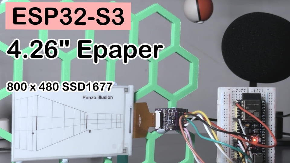
One-line summary: Hook up 8 wires, install 2 libraries, flash one sketch — and your ESP32-S3 plays the Ponzo corridor illusion on a 4.26“ e-paper display, teaching you partial refresh (the most useful e-paper skill) along the way.
Difficulty: ⭐⭐☆☆☆ (beginner-friendly, as long as you don't wire VCC to 5V)
Time needed: 40 minutes (10 wiring + 15 environment setup + 15 flashing & watching)
Tested with: Arduino IDE 2.3.8 + ESP32 Arduino Core 3.3.10 + GxEPD2 1.6.9
TL;DR (quick start):
- Wiring: MOSI → GPIO11, SCK → GPIO12, CS → GPIO10, DC → GPIO9, RST → GPIO8, BUSY → GPIO7
- VCC goes to 3.3V (5V will kill the panel — don’t ask how I know)
- Install two libraries: GxEPD2 (≥ 1.5.3) + Adafruit_GFX (comes along automatically with GxEPD2)
- Select “ESP32S3 Dev Module” as the board, flash, and wait for your brain to get fooled
Intro: A Corridor That Has Fooled Humanity for Over 100 Years
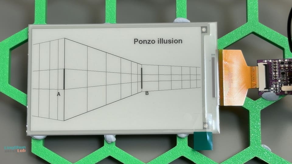
You’ve definitely seen this picture: two identical line segments, but once corridor perspective lines are drawn around them, the “farther” one looks longer. You know they’re equal, yet your eyes refuse to admit it — that’s the classic Ponzo illusion. Your brain automatically switches on “perspective inference” mode and translates “far away” into “bigger.”
I’d been looking for a chance to make this illusion physical. I happened to have a 4.26“ EPD0426A02 e-paper display (800×480, SSD1677 controller) and an ESP32-S3 on my desk. E-paper’s personality — slow changes, and it keeps the image even with power off — is a perfect match for an illusion demo: the audience gets plenty of time to question reality, and afterwards you can unplug it and leave it on the desk to fool the next guest.
This article walks you through everything from scratch: connect 8 wires, install 2 libraries, flash one sketch, and let this e-paper display teach your brain a lesson. Along the way you’ll max out the most practical e-paper skill — partial refresh.
Final Result
After flashing, the display automatically plays a ~40-second, four-frame animation: it first asks “are these two lines the same length?”, then reveals the answer, and finally rests on the corridor illusion image (the MCU goes idle; the image stays until you manually reset).
Here’s the four-frame storyboard. Partial refresh transitions between frames while the line segments themselves never move:
| Frame | Content | Duration |
|---|---|---|
| 1 | Only segments A and B, “Are these two lines the same length?” | 7 s |
| 2 | Horizontal dashed guide lines appear, “Yes - exactly equal.” | 7 s |
| 3 | Perspective lines enter, “And now?” | 10 s |
| 4 | Guides + perspective together, “Same lines - your brain was fooled.” | 7 s |
| Finale | Pure illusion scene + big title “Ponzo illusion”, then idle | Holds |
Component Overview
EPD0426A02 E-Paper Display — An “Electronic Blackboard” That Remembers Without Power
The EPD0426A02 is a 4.26-inch e-paper display module made by Osptek (Shenzhen). Its job is to “print” the image data sent by the ESP32-S3 onto the screen. In this project it plays the four-frame illusion animation and holds the image for the long term.
In everyday terms: it’s a cousin of the Kindle screen — an “electronic blackboard.” Write on it, cut the power, and the writing stays; to change the content you erase and rewrite the whole screen (that’s why e-paper blinks a few times during refresh). Slow refresh is its character; not consuming power is its superpower.
Key specs:
| Item | Spec |
|---|---|
| Size / Resolution | 4.26 inch, 800 × 480 (landscape), 219 DPI |
| Driver IC | SSD1677 (960 source × 680 gate controller, SPI interface) |
| Display capability | B/W bi-stable, native 4-level grayscale (2 bit/px) |
| Interface | 24-pin FPC, 4-wire SPI (write-only) |
| Peak refresh current | ~50 mA |
| Deep sleep current | ~3 µA (image held with zero power) |
| Rated lifetime | 5 years / 1,000,000 refreshes (25 ℃ / 60%RH) |
Why this one? 800×480 is high-definition for an e-paper of this size — perspective lines come out razor sharp; 3 µA deep sleep means “finish the show, unplug, keep fooling people” costs zero battery; and GxEPD2 has supported it natively since v1.5.3 (driver class GxEPD2_426_GDEQ0426T82), so you don’t have to write any driver code.
Pin Description
The EPD0426A02 adapter board breaks out 8 pins, each with its own job:
| Pin | What it does |
|---|---|
| VCC | 3.3V power (⚠️ never connect to 5V) |
| GND | Common ground — speak the same language as the board |
| MOSI (DIN) | SPI data — the MCU pushes pixels into the panel |
| SCK (SCL) | SPI clock — agrees on how fast each bit is sent |
| CS | Chip select — pulled low = “this bus is yours now” |
| DC | Data/Command switch: high = pixel data, low = command |
| RST | Hardware reset — toggled once before init |
| BUSY | Busy signal: high = refreshing, do not disturb |
One heads-up: this panel’s BUSY is active-high (busy = high), even though the pin is often labeled BUSY_N — the exact opposite of intuition. Luckily GxEPD2 has already filled that pothole for us; just be aware it exists.
BOM
| # | Component | Model / Spec | Qty | Notes |
|---|---|---|---|---|
| 1 | Dev board | ESP32-S3 (ESP32-S3-DevKitC / Arduino Nano ESP32 both fine) | 1 | Onboard USB-to-serial is all you need |
| 2 | E-paper module | EPD0426A02 (SSD1677, 800×480) | 1 | Comes with adapter board, 8 header pins |
| 3 | Dupont wires | Female-to-female or male-to-male | 8 | 6 signals + power/ground |
| 4 | USB cable | Type-C or Micro (depends on the board) | 1 | Power + flashing |
Wiring
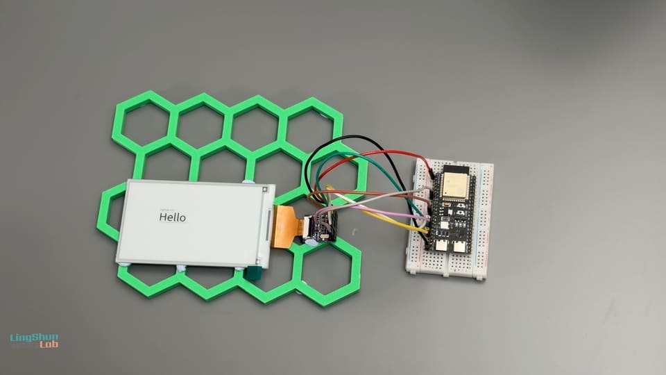
The wiring diagram is the source of truth; the table is a cross-check:
| E-paper pin | ESP32-S3 GPIO | Notes |
|---|---|---|
| VCC | 3V3 | ⚠️ 3.3V — 5V kills the panel |
| GND | GND | Any GND |
| MOSI (DIN) | GPIO11 | SPI data |
| SCK (SCL) | GPIO12 | SPI clock |
| CS | GPIO10 | Chip select |
| DC | GPIO9 | Data/Command |
| RST | GPIO8 | Reset |
| BUSY | GPIO7 | Busy signal (input) |
After wiring, double-check every connection — this saves you 80% of debugging time. A miswired e-paper doesn’t throw errors or smoke; it just silently shows a white or garbled screen — you can’t tell whether the code or the wiring is wrong. Also note: on the ESP32-S3, the Arduino framework’s default I2C pins are GPIO8 (SDA) and GPIO9 (SCL), which this sketch assigns to RST and DC. So once the display is connected, any I2C device must be remapped to other free GPIOs via Wire.begin(SDA, SCL).
If you’re using an Arduino Nano ESP32, the D4~D7 and A4/A5 silkscreen labels are not the real GPIO numbers. Mapping table:
| E-paper pin | Real GPIO | Nano ESP32 silkscreen |
|---|---|---|
| MOSI | GPIO11 | A4 |
| SCK | GPIO12 | A5 |
| CS | GPIO10 | D7 |
| DC | GPIO9 | D6 |
| RST | GPIO8 | D5 |
| BUSY | GPIO7 | D4 |
Libraries to Install
Open Arduino IDE → Tools → Manage Libraries, and install:
| Library | Author | Version requirement | Purpose |
|---|---|---|---|
| esp32 | Espressif Systems | 3.3.10 (verified with Arduino IDE 2.3.x) | ESP32-S3 board support |
| GxEPD2 | Jean-Marc Zingg | 1.6.9 (includes the GxEPD2_426_GDEQ0426T82 driver class) |
E-paper driver |
| Adafruit_GFX | Adafruit | Auto-installed with GxEPD2 | Graphics API (lines, fonts) |
Then select ESP32S3 Dev Module under Tools → Board, plug in the serial port, and you’re ready to flash.
Complete Code
Copy and flash directly (the file corresponds to arduino/GxEPD2_CorridorIllusion/GxEPD2_CorridorIllusion.ino in the project):
/*
 * EPD0426A02 (4.26" 480x800 SPI e-paper, SSD1677) — Corridor Illusion (Ponzo Illusion) demo
 * Board: ESP32-S3 (Arduino IDE, select "ESP32S3 Dev Module")
 * Driver library: GxEPD2, using the built-in driver class GxEPD2_426_GDEQ0426T82
 *
 * Pin definitions identical to the reference example:
 *   BUSY -> GPIO7    DC -> GPIO9     CS -> GPIO10
 *   SCK  -> GPIO12   MOSI -> GPIO11  RST -> GPIO8
 *
 * Show sequence (single run, no loop):
 *   Frame 1: two equal thick segments A & B       "Are these two lines the same length?"
 *   Frame 2: dashed horizontal guides added       "Yes - exactly equal."
 *   Frame 3: segments stay, corridor perspective  "And now?"
 *   Frame 4: perspective + guides, the reveal     "Same lines - your brain was fooled."
 *   Finally back to frame 3 (illusion scene), hold
 *
 * The canvas is landscape 800x480 (rotation 0 = controller native orientation).
 */

#include <Arduino.h>
#include <SPI.h>
#include <GxEPD2_BW.h>
#include <Fonts/FreeSansBold12pt7b.h>
#include <Fonts/FreeSansBold18pt7b.h>

// ---------------- Pin definitions (match ESP-IDF project board_pins.h) ----------------
#define EPD_CS   10
#define EPD_DC   9
#define EPD_RST  8
#define EPD_BUSY 7
#define EPD_SCK  12
#define EPD_MOSI 11

// Full-screen buffer mode (page_height = HEIGHT, 48000 bytes)
GxEPD2_BW<GxEPD2_426_GDEQ0426T82, GxEPD2_426_GDEQ0426T82::HEIGHT> display(
  GxEPD2_426_GDEQ0426T82(/*CS=*/EPD_CS, /*DC=*/EPD_DC, /*RST=*/EPD_RST, /*BUSY=*/EPD_BUSY));

// ---------------- Scene geometry (800x480 landscape) ----------------
static const int16_t W = 800;
static const int16_t H = 480;

static const int16_t VPX = 700, VPY = 240;   // vanishing point, left corridor
static const int16_t VP2X = 1600, VP2Y = 240; // 2nd vanishing point (far right off-screen), right wall lines
static const int16_t VP0X = -900, VP0Y = 260; // 3rd vanishing point (far left off-screen), left wall lines
static const int16_t XN  = 150;              // near corner x (segment A)
static const int16_t XF  = 520;              // far corner x (segment B)
static const int16_t Y1  = 190;              // segment top endpoint
static const int16_t Y2  = 290;              // segment bottom endpoint (both segments are 100px long)

static const int16_t SEG_W = 6;              // segment thickness
static const uint32_t FRAME_MS  = 7000;      // per-frame hold time
static const uint32_t FRAME3_MS = 10000;      // frame 3 holds a bit longer

// Experiment: the datasheet requires VCOM control register (0x2B) to be fixed at 0x04, 0x63;
// the GxEPD2 driver doesn't send it, so we patch it manually
// (must be called after display.init(), because SWRESET clears this register)
static void epdWriteVCOMControl()
{
  SPI.beginTransaction(SPISettings(4000000, MSBFIRST, SPI_MODE0));
  digitalWrite(EPD_CS, LOW);
  digitalWrite(EPD_DC, LOW);
  SPI.transfer(0x2B);
  digitalWrite(EPD_DC, HIGH);
  SPI.transfer(0x04);
  SPI.transfer(0x63);
  digitalWrite(EPD_CS, HIGH);
  SPI.endTransaction();
}

// y value of the point at x on the line from (px, py) towards vanishing point (vpx, vpy)
static int16_t onLineYVP(int16_t x, int16_t px, int16_t py, int16_t vpx, int16_t vpy)
{
  float t = (float)(x - px) / (float)(vpx - px);
  return (int16_t)(py + (vpy - py) * t);
}

// Left corridor: towards vanishing point VP
static int16_t onLineY(int16_t x, int16_t px, int16_t py)
{
  return onLineYVP(x, px, py, VPX, VPY);
}

// Right wall: towards 2nd vanishing point VP2
static int16_t onLineY2(int16_t x, int16_t px, int16_t py)
{
  return onLineYVP(x, px, py, VP2X, VP2Y);
}

// Left wall: towards 3rd vanishing point VP0
static int16_t onLineY0(int16_t x, int16_t px, int16_t py)
{
  return onLineYVP(x, px, py, VP0X, VP0Y);
}

// ---------------- Drawing elements ----------------

// The two segments — identical coordinates and thickness in every frame
static void drawSegments()
{
  display.fillRect(XN - SEG_W / 2, Y1, SEG_W, Y2 - Y1 + 1, GxEPD_BLACK); // segment A
  display.fillRect(XF - SEG_W / 2, Y1, SEG_W, Y2 - Y1 + 1, GxEPD_BLACK); // segment B

  display.setFont(&FreeSansBold12pt7b);
  display.setTextColor(GxEPD_BLACK);
  display.setCursor(XN - 34, Y2 + 30);
  display.print("A");
  display.setCursor(XF + 16, Y2 + 30);
  display.print("B");
}

// Horizontal dashed alignment guides, proving both segment endpoints share the same baseline
static void drawGuides()
{
  const int16_t ys[2] = {Y1, Y2};
  for (int i = 0; i < 2; i++)
  {
    for (int16_t x = 0; x < W; x += 12)
    {
      display.drawFastHLine(x, ys[i], 6, GxEPD_BLACK);
    }
  }
}

// Corridor perspective lines
static void drawPerspective()
{
  const int16_t topX = XN, topY = 40;    // near corner top
  const int16_t botX = XN, botY = 440;   // near corner bottom

  int16_t ftY = onLineY(XF, topX, topY); // far corner top y
  int16_t fbY = onLineY(XF, botX, botY); // far corner bottom y

  // Ceiling / floor (2px)
  display.drawLine(topX, topY, XF, ftY, GxEPD_BLACK);
  display.drawLine(topX, topY + 1, XF, ftY + 1, GxEPD_BLACK);
  display.drawLine(botX, botY, XF, fbY, GxEPD_BLACK);
  display.drawLine(botX, botY - 1, XF, fbY - 1, GxEPD_BLACK);

  // Near corner (2px) / far corner (1px)
  display.drawLine(XN, topY, XN, botY, GxEPD_BLACK);
  display.drawLine(XN + 1, topY, XN + 1, botY, GxEPD_BLACK);
  display.drawLine(XF, ftY, XF, fbY, GxEPD_BLACK);

  // Horizontal perspective lines through the segment endpoints (extending to the far wall)
  const int16_t ys[2] = {Y1, Y2};
  for (int i = 0; i < 2; i++)
  {
    display.drawLine(XN, ys[i], XF, onLineY(XF, XN, ys[i]), GxEPD_BLACK);
  }

  // Vertical divisions (wall brick seams)
  static const int16_t divX[] = {260, 350, 420, 470, 500};
  for (uint8_t i = 0; i < sizeof(divX) / sizeof(divX[0]); i++)
  {
    int16_t x = divX[i];
    display.drawLine(x, onLineY(x, topX, topY), x, onLineY(x, botX, botY), GxEPD_BLACK);
  }

  // ---- Right wall: from far corner (XF) to the right screen edge, converging on VP2 ----
  const int16_t XR = W - 1;

  // Ceiling line / floor line (continued to the right edge)
  display.drawLine(XF, ftY, XR, onLineY2(XR, XF, ftY), GxEPD_BLACK);
  display.drawLine(XF, fbY, XR, onLineY2(XR, XF, fbY), GxEPD_BLACK);

  // Horizontal lines through the segment endpoints, continued on the right wall
  for (int i = 0; i < 2; i++)
  {
    int16_t yAtXF = onLineY(XF, XN, ys[i]); // y where the left-wall perspective line reaches the far corner
    display.drawLine(XF, yAtXF, XR, onLineY2(XR, XF, yAtXF), GxEPD_BLACK);
  }

  // Right wall vertical divisions (brick seams), connecting ceiling and floor lines
  static const int16_t divXR[] = {600, 660, 710, 750, 780};
  for (uint8_t i = 0; i < sizeof(divXR) / sizeof(divXR[0]); i++)
  {
    int16_t x = divXR[i];
    display.drawLine(x, onLineY2(x, XF, ftY), x, onLineY2(x, XF, fbY), GxEPD_BLACK);
  }

  // ---- Left wall: from near corner (XN) to the left screen edge, converging on VP0 ----
  const int16_t XL = 0;

  // Ceiling line / floor line (continued to the left edge)
  display.drawLine(XN, topY, XL, onLineY0(XL, XN, topY), GxEPD_BLACK);
  display.drawLine(XN, botY, XL, onLineY0(XL, XN, botY), GxEPD_BLACK);

  // Horizontal lines through the segment endpoints, continued on the left wall
  for (int i = 0; i < 2; i++)
  {
    display.drawLine(XN, ys[i], XL, onLineY0(XL, XN, ys[i]), GxEPD_BLACK);
  }

  // Left wall vertical divisions (brick seams)
  static const int16_t divXL[] = {30, 80, 120};
  for (uint8_t i = 0; i < sizeof(divXL) / sizeof(divXL[0]); i++)
  {
    int16_t x = divXL[i];
    display.drawLine(x, onLineY0(x, XN, topY), x, onLineY0(x, XN, botY), GxEPD_BLACK);
  }
}

// Top caption
static void drawTitle(const char *text)
{
  display.setFont(&FreeSansBold12pt7b);
  display.setTextColor(GxEPD_BLACK);
  display.setCursor(20, 34);
  display.print(text);
}

// Big title for the final hold frame: larger font, horizontally centered at the top
// (the top center area sits above the ceiling line, so it never overlaps the perspective lines)
static void drawTitleBig(const char *text)
{
  display.setFont(&FreeSansBold18pt7b);
  display.setTextColor(GxEPD_BLACK);
  int16_t tbx, tby;
  uint16_t tbw, tbh;
  display.getTextBounds(text, 0, 0, &tbx, &tby, &tbw, &tbh);
  display.setCursor((W - tbw) / 2 - tbx + 200, 48 - tby); // baseline around y=48
  display.print(text);
}

// Draw the whole scene by frame number (1..4), always full-window absolute coordinates
static void drawFrame(uint8_t frame)
{
  display.fillScreen(GxEPD_WHITE);
  switch (frame)
  {
    case 1:
      drawTitle("Are these two lines the same length?");
      break;
    case 2:
      drawTitle("Yes - exactly equal.");
      drawGuides();
      break;
    case 3:
      drawTitle("And now?");
      drawPerspective();
      break;
    case 5: // final hold frame: illusion scene + big title, no "And now?"
      drawTitleBig("Ponzo illusion");
      drawPerspective();
      break;
    case 4:
    default:
      drawTitle("Same lines - your brain was fooled.");
      drawPerspective();
      drawGuides();
      break;
  }
  drawSegments(); // always drawn last in every frame, coordinates never change
}

// Show a frame with full refresh
static void showFrameFull(uint8_t frame)
{
  display.setFullWindow();
  drawFrame(frame);
  display.display(); // full refresh
}

// Show a frame with partial refresh: draw full window, use displayWindow() to refresh
// only the changed region (full-screen window = full-screen partial refresh)
static void showFramePartial(uint8_t frame)
{
  display.setFullWindow();
  drawFrame(frame);
  display.displayWindow(0, 0, W, H);
}

void setup()
{
  Serial.begin(115200);
  delay(500);
  Serial.println("[EPD] EPD0426A02 Corridor Illusion (GxEPD2 / GDEQ0426T82)");

  // ESP32 custom SPI pin mapping: SCK, MISO(-1 = unused), MOSI, SS
  SPI.begin(EPD_SCK, -1, EPD_MOSI, EPD_CS);

  display.init(115200);
  display.setRotation(0); // native landscape 800x480
  display.setTextColor(GxEPD_BLACK);

  epdWriteVCOMControl(); // patch the 0x2B VCOM control register

  // ---- Single run: frame 1 -> 2 -> 3 -> 4 ----
  // Frame 1: opening with full refresh
  showFrameFull(1);
  Serial.println("[EPD] frame 1 (full refresh)");
  delay(FRAME_MS);

  // Frames 2 -> 3 -> 4: partial refresh, segments rock solid
  showFramePartial(2);
  Serial.println("[EPD] frame 2 (partial)");
  delay(FRAME_MS);

  showFramePartial(3);
  Serial.println("[EPD] frame 3 (partial)");
  delay(FRAME3_MS);

  showFramePartial(4);
  Serial.println("[EPD] frame 4 (partial, reveal)");
  delay(FRAME_MS);

  // Finally hold on the illusion scene (frame 5: corridor + big title "Ponzo illusion", no "And now?")
  showFramePartial(5);
  Serial.println("[EPD] final frame 5 (illusion + title), hold");
  delay(1000);

  // Demo over, image stays on screen (no deep sleep used)
  Serial.println("[EPD] done, holding frame");
}

void loop()
{
  // Image already held on screen; just idle here
}
Code Walkthrough
The sketch is 300-some lines — looks long, but it only does six things:
- Pins and display object (the
#definegroup +GxEPD2_BWdeclaration): 6 macros map to the 6 signal wires;GxEPD2_BW<..., HEIGHT>is “full-screen buffer mode” — an entire 48,000-byte frame lives in RAM at once, which the ESP32-S3 handles without breaking a sweat. Want different pins? Just edit those 6 macros. - Four-frame storyboard (
drawFrame): basically a switch table. Note thatdrawSegments()sits outside the switch and is drawn last in every frame — the segment coordinates never change; only the surrounding guides and perspective lines do. That’s the iron rule that makes the illusion honest. - Perspective math (
drawPerspective+ the threeonLineYfunctions): at its core, a single two-point line equation from middle school. Each of the three walls converges on its own “vanishing point” (an intersection off-canvas), which gives the lines natural depth. Placing vanishing points outside the screen (VP2 at x=1600, VP0 at x=-900) actually makes the perspective look more natural. - Partial refresh (
displayWindowinsideshowFramePartial): redraw the whole frame in memory first, then push only the changed pixels to the panel. Between frames 2 and 4 the segments on screen don’t move a hair — only the guides and perspective lines flash. That’s the soul of partial refresh vs. full refresh: fast (~0.42 s per update) and no eye-searing blinking. - The 0x2B VCOM patch (
epdWriteVCOMControl): the SSD1677 datasheet requires writing0x04, 0x63to register0x2B(to suppress glitches when ACVCOM toggles), but neither GxEPD2 nor the vendor demo sends this command. The consequence of skipping it is sneaky: after the demo ends, as long as VCC stays connected, the image slowly degrades over minutes. You must re-send it after everydisplay.init(), because the software reset (0x12) clears that register. This pitfall cost me a whole day — see the troubleshooting section.
Troubleshooting
Don’t panic — 90% of problems come from these five spots. Check them top to bottom:
1. White screen after flashing, nothing shows
Don’t question your life choices yet. Check in order of probability: ① Are any of the 6 signal wires loose (Dupont wires wiggle loose on breadboards over time)? ② Is VCC really on 3.3V? ③ Does the serial monitor print [EPD] frame 1 right after flashing — if there’s no serial output at all, the program isn’t running and the panel is innocent. E-paper never throws errors; a white screen is its error message.
2. Compile error: 'GxEPD2_426_GDEQ0426T82' does not name a type
Your GxEPD2 is older than 1.5.3. Open the Library Manager and upgrade GxEPD2 to the latest version — this driver class only exists since v1.5.3.
3. The demo finished, but the image slowly degrades while sitting there (over ~ten minutes)
That’s the 0x2B issue. Make sure epdWriteVCOMControl() is called after every display.init() — software reset wipes that register, so init first, patch second; get the order wrong and it’s as if you never sent it. With the patch in place, a powered idle image stays rock solid.
4. Only half the image shows, or it’s vertically offset
Nine times out of ten it’s the rotation or resolution. This sketch uses setRotation(0) (native landscape 800×480); if a previous sketch left rotation at 1 or 3, set it back. (The ESP-IDF side has a paged-rendering variant for tight memory; Arduino’s full-screen buffer mode doesn’t have this problem.)
5. Upload failed / serial port not found
Hold the BOOT button on the dev board while plugging in USB to enter download mode. If that still fails, swap the cable — many “charging cables” carry power only, no data wires. That’s the most frequent crash of my flashing career.
FAQ
Q: Can a regular ESP32 (not S3) or ESP32-C3 run this sketch? A: Yes. The code uses nothing S3-specific; any ESP32 family chip supported by the Arduino framework works — just move the wires to free GPIOs on your board. The full-screen buffer needs about 48 KB of RAM, which even the classic ESP32 (520 KB SRAM) can afford.
Q: Can I use different GPIO pins? How?
A: Sure. Edit the 6 #defines at the top of the sketch (EPD_CS / EPD_DC / EPD_RST / EPD_BUSY / EPD_SCK / EPD_MOSI) and rewire to match. On the ESP32-S3, avoid strapping pins GPIO0/3/45/46, GPIO19/20 (USB), and pins occupied by Flash/PSRAM — check your board’s schematic for details.
Q: E-paper takes seconds to refresh and blinks a few times — is that normal?
A: Slow full refresh is just physics: every refresh re-“presses” all 480 rows of pixels. A full refresh on this panel measures about 2 seconds (about 1.5 s with fast waveforms). The blinking is the standard ghost-erasing procedure, not a defect. If it’s too slow for you, use partial refresh (displayWindow) like this sketch — measured at about 0.42 s per update with almost no flashing.
Q: Can the panel take 5V? A: No. The EPD0426A02’s VCC must be 3.3V, period. 5V won’t make it smoke instantly, but it damages the panel’s internal high-voltage driver circuit — symptoms show up as localized garbling after a few uses, and it’s not covered by warranty. Better a dark screen than 5V.
Q: The screen slowly degrades when left powered after the demo — how do I fix it for good?
A: Write the two bytes 0x04, 0x63 to the SSD1677’s 0x2B register (the datasheet literally says “reduce glitch when ACVCOM toggle”), and re-send after every software reset. That’s exactly what epdWriteVCOMControl() does in the sketch. A more physical alternative is cutting VCC with a P-MOSFET, but when two bytes of software fix it, there’s no need to heat up the soldering iron.
Q: Why do you say 4-level grayscale? The product page advertises 16 levels! A: SSD1677 pixels physically have only black/white stable states, and the data path is 2 bit/px — natively that’s 4 gray levels (black / dark gray / light gray / white). Grayscale comes from waveform tables (LUTs) applying pulses of different counts and polarities to different pixels within one frame; the perceived 16 levels are simulated on top of the native 4 via Bayer 4×4 ordered dithering. This illusion sketch uses pure black and white, so it’s unaffected — but remember this ceiling when you want to show photos.
Q: Partial refresh leaves ghosting over time — what do I do?
A: Ghosting accumulation is inherent to how partial refresh works. The practical strategy is “do a full refresh after a run of partials” — display.clearScreen(), or simply flash full black then full white once to wash the ghosts away. This sketch only refreshes 4 times, so ghosting is negligible.
Q: I want to change the segment lengths/positions, or switch the captions to another language — where do I edit?
A: All segment parameters live in the “Scene geometry” constant group: XN/XF are the horizontal positions, Y1/Y2 the top/bottom endpoints (length = Y2 - Y1), SEG_W the thickness. Captions live in the drawFrame switch. After editing, keep the two segments’ coordinates consistent — otherwise the illusion stops being “honest.”
Going Further
- Swap the illusion: replace Ponzo with the Müller-Lyer arrow illusion or the Ebbinghaus size illusion — just rewrite the geometry functions in
drawFrame - Manual frame advance: hook up a touch button or potentiometer so the audience shouts “reveal!” to trigger frame 3 — maximum ceremony
- Partial-refresh stopwatch: reuse this sketch’s
displayWindowtrick to build an e-stopwatch ticking every 0.42 s, and enjoy the cognitive dissonance of e-paper doing “motion” - Grayscale photos: bring in GxEPD2_4G, and “print” a photo onto e-paper with 4-level gray + Bayer dithering — Kindle wallpaper vibes
- Battery-powered desk piece: 18650 + deep sleep, waking for a few seconds a day to update the image — one cell lasts months, and your illusion corridor can fool people 24/7
References
- SSD1677 driver IC official product page (Solomon Systech): https://www.solomon-systech.com/product/ssd1677/
- GxEPD2 driver library on GitHub (full supported-panel list): https://github.com/ZinggJM/GxEPD2
- Adafruit_GFX graphics library on GitHub: https://github.com/adafruit/Adafruit-GFX-Library
- ESP32-S3 SoC official product page (Espressif): https://www.espressif.com/en/products/socs/esp32-s3
- Sister library GxEPD2_4G (if you want 4-level gray + dithered grayscale photos): https://github.com/ZinggJM/GxEPD2_4G