Driving an ST7306 4-Color Reflective LCD with ESP32-S3: Complete Arduino IDE + SPI Guide
Drive an ST7306 4-color reflective LCD with an ESP32-S3 using the Arduino IDE and SPI: 21-pin FPC wiring, complete code, display orientation tweaks, and blank-display troubleshooting. Tested with Arduino IDE 2.3.8 + esp32 Core 3.3.8.
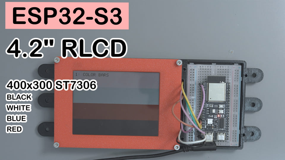
Difficulty: ⭐⭐☆☆☆
Estimated time: about 30–60 minutes (excluding downloads and hardware debugging)
Test environment: Arduino IDE v2.3.8 + esp32 Arduino Core v3.3.8
TL;DR: Getting Started with ESP32-S3 + ST7306
- The module runs on 3.3V only. Connect both FPC pins 5 and 6 to 3.3V, wire a solid common ground, and never feed it 5V.
- Default
PINSET = 1: CS→GPIO9, RESET→GPIO10, SCLK→GPIO12, MOSI→GPIO13, RS/D/C→GPIO14; TE can be left unconnected. - Install
esp32 by Espressif Systemsin the Arduino IDE — no separate ST7306 library needed. - Open
esp32s3-st7306-bringup.inofrom the project directory and pick the board that matches your ESP32-S3 (here it’sESP32S3 Dev Module). If the serial monitor shows no logs, checkUSB CDC On Bootfirst. - SPI defaults to mode 0 at 20MHz, with a 400×300 logical landscape canvas. If nothing shows: power down and verify the common ground, FPC orientation, and RS pin; then power up, measure 3.3V, and look at the panel under bright light. If it’s still blank, drop
SPI_HZto 10MHz.
Preface: Light Up the ST7306 with the Arduino IDE First
This 4.2-inch panel uses the ST7306 controller and receives commands and framebuffer data over SPI. It’s a fully reflective TFT LCD — no backlight, readable in ambient light — so you need a bright environment to see it clearly. The project directory ships both ESP-IDF and Arduino IDE programs; this article follows the Arduino IDE path only: wire up the 21-pin FPC, flash the example, and get the 400×300 landscape test pages running. The ESP-IDF 20-page demo is still in the project directory if you want to dig into the driver wrapper and drawing functions and build it yourself.
Final Result: The ST7306’s 8-Page Display Test
Once wiring and flashing are correct, the program cycles through 8 test pages. Regular pages stay for about 3 seconds; the moving-square page stays about 6 seconds. Open the serial monitor at 115200 baud to see the init and page-flip logs. Every page is continuously redrawn while it’s displayed; if you opened the serial monitor only after uploading, you may miss the boot logs — just press RST on the board to see them again.
| Page | Test content | What to check | Name in code |
|---|---|---|---|
| 0 | White, cyan, red, black horizontal bars | All four display states | PAGE_COLOR_BARS |
| 1 | HELLO WORLD, border, corner marks | Text and landscape orientation | PAGE_HELLO |
| 2 | Time, frame count, FPS | Uptime since boot, global frame count, cumulative average FPS (not this page’s own frame rate) | PAGE_COUNTER |
| 3 | Diagonals, horizontal and vertical lines | Lines and coordinate mapping | PAGE_DIAGONAL |
| 4 | Square bouncing left and right | Continuous refresh | PAGE_REFRESH |
| 5 | Checkerboard | Black/white cells (20 pixels per cell) | PAGE_CHECKER |
| 6 | Horizontal stripes | Regular pattern | PAGE_STRIPES |
| 7 | CYAN color test | Full-screen cyan (looks bluish), framebuffer byte 0x33 |
PAGE_CYAN |
Note: the on-screen page labels (like
1: COLOR BARS,3: DIAGONAL) are hard-coded strings in the code and don’t fully match the page numbers in the table above (COLOR BARS is page 0). Trust the[PAGE]serial logs.
Parts Overview: YDP420H005-V3 and ST7306
The YDP420H005-V3 Reflective LCD Module
This is a 4.2-inch fully reflective TFT LCD module with a native panel framebuffer of 300×400. The ST7306 controller is already integrated in the module; the ESP32-S3 sends commands and pixel data over SPI. The Arduino program in this project maps it at the application layer into a 400×300 landscape canvas.
The firmware drives four display states with 2-bit encoding: white, cyan, red, black (0x00–0x03). Each pixel takes 2 bits, with no intermediate gray levels. Don’t blindly copy colors and init parameters from other ST7306 panels.
| Parameter | This project’s module |
|---|---|
| Model | Osptek YDP420H005-V3 |
| Controller | Sitronix ST7306 |
| Native resolution | 300×400 |
| Display states | White, cyan, red, black; 2 bits/pixel |
| Host interface | 4-wire SPI (SCLK, MOSI, CS, D/C), plus RESET and optional TE; no MISO/SDO on the FPC — write-only, no readback |
| Module power & logic | 3.3V |
| Active display area | 63.6×84.8mm |
| Operating temperature | −20 to +70°C |
The 21-Pin FPC Breakout Board
The panel exposes its signals through a 21-pin FPC. A breakout board turns those fine-pitch contacts into solder pads or pin headers that are easy to wire to an ESP32-S3; this project needs no extra display driver circuitry.
I used the dual-FPC universal breakout board the vendor sells alongside the panel; it has no model number silkscreened on it. There are two connectors on the board: a 21-pin one for the 4.2-inch panel and a 12-pin one for a 2.9-inch panel, plus GND and 3V3 pads nearby.
A few tiny SMD components are soldered next to each FPC connector — very small packages with no value markings. I haven’t looked up what they do or their values.
This universal board has one easy-to-get-wrong spot: it carries both RS and DC silkscreen labels. This module’s LCD_D/C goes to the pad marked RS; the other DC label is unrelated to this module (I haven’t verified which connector it belongs to) — don’t wire to it. When buying or soldering a breakout board, also double-check the FPC contact orientation and pin numbering.
Pin Reference: The YDP420H005-V3’s 21-Pin FPC
The table below follows the module’s FPC numbering. Breakout-board silkscreen may differ — when wiring, go by the module datasheet and the actual traces on your breakout board (this one has no model number and no public schematic).
| FPC pin | Module signal | Common silkscreen | Usage in this build |
|---|---|---|---|
| 1, 4, 7, 14 | GND | GND | Connect to common ground |
| 2, 3 | NC | NC | Leave unconnected |
| 5, 6 | VCC(3.3V) | VCC, VCI | Connect both pins to 3.3V |
| 8 | LCD_RES | RESET, RST | GPIO10, active-low reset |
| 9 | LCD_SCLK | SCL, SCLK | GPIO12, SPI clock |
| 10 | TE | TE | Can go to GPIO11; not read in this example, may float |
| 11 | LCD_SDI | SDA, MOSI | GPIO13, SPI MOSI |
| 12 | LCD_D/C | RS, A0 | GPIO14, selects command vs data |
| 13 | LCD_CS | CS | GPIO9, active-low chip select |
| 15–19 | TP-VDD, TP-RST, TP-INT, TP-SDA, TP-SCL | Touch-related labels | This module has no touch; leave unconnected |
| 20, 21 | GND | GND | Also ground; connecting 1, 4, 7, 14 is enough here (I haven’t measured one by one whether 20 and 21 are tied to them on the breakout board — ground them too if you want to be safe) |
The SCL and SDA labels here are just common names left over from breakout silkscreen conventions. This build uses SPI: SCL corresponds to the panel’s serial clock, and SDA corresponds to MOSI.
BOM: What You Need to Wire Up the ST7306
| Component | Spec | Qty | Notes |
|---|---|---|---|
| ESP32-S3 dev board | ESP32-S3 N16R8 (16MB Flash / 8MB PSRAM) | 1 | Uses 3.3V GPIO |
| Display module | Osptek YDP420H005-V3 | 1 | 4.2-inch, 21-pin FPC |
| FPC breakout board | Vendor’s dual-FPC universal board, no model number | 1 | Verify pin numbering and contact orientation |
| USB cable | Matches the board’s connector | 1 | Must support data transfer |
| Wires | Short jumper wires or soldered wires | Several | Shorter SPI wires are more reliable and easier to tidy |
Wiring: ESP32-S3 to ST7306
Power everything down first, then wire according to the default PINSET = 1 below.
| FPC pin | Panel signal | ESP32-S3 | Required | Notes |
|---|---|---|---|---|
| 13 | LCD_CS / CS | GPIO9 | Required | Chip select |
| 8 | LCD_RES / RESET | GPIO10 | Required | Hardware reset |
| 10 | TE | GPIO11 | Optional | Not read by the example, may float |
| 9 | LCD_SCLK / SCLK | GPIO12 | Required | SPI clock |
| 11 | LCD_SDI / MOSI | GPIO13 | Required | SPI data out |
| 12 | LCD_D/C / RS | GPIO14 | Required | Wire to RS on the vendor breakout board |
| 5, 6 | VCC / VCI | 3.3V | Required | Connect both power pins |
| 1, 4, 7, 14 | GND | GND | Required | Common ground with the dev board |
⚠️ Both module power and logic are 3.3V. When the module is unpowered, don’t keep feeding it signals from GPIO either.
After wiring, check with the power off first:
- Confirm FPC pin 1 and the contact orientation against the module’s mechanical drawing.
- Use a multimeter in continuity mode to confirm the dev board’s GND is connected to the panel’s GND pins, and that there’s no short between 3.3V and GND.
- Verify the five signal wires — CS, RESET, SCLK, MOSI, RS — one by one.
- On the vendor’s dual-FPC breakout board, double-check that GPIO14 goes to RS.
- Check for loose connections or shorts.
Then check with the power on:
- Measure the voltage at pins 5 and 6 (or the corresponding breakout pads) with a multimeter; it should read 3.3V. If not, power down immediately and investigate.
I recommend going over every wire twice against the tables. If one wire is wrong, the serial logs won’t tell you which one (this example’s serial logs don’t reflect panel state — see the troubleshooting section).
What to Install: ESP32-S3 Support in the Arduino IDE
There’s no standalone ST7306 Arduino library for this example. The driver, drawing code, and test pages all live in the .ino file. SPI.h and esp_heap_caps.h come with the ESP32 Arduino Core — no need to search for them in the Library Manager.
| Name | Author or source | How to install | Version confirmed here |
|---|---|---|---|
| Arduino IDE | Arduino | Install from the Arduino website | v2.3.8 |
| esp32 Arduino Core | Espressif Systems | Arduino IDE Boards Manager | v3.3.8 |
| SPI | Bundled with the Espressif Arduino Core | Installed with the Core | Ships with Core v3.3.8 |
| esp_heap_caps | Bundled with the Espressif Arduino Core | Installed with the Core | Ships with Core v3.3.8 |
Installing the esp32 Arduino Core
-
Open the Arduino IDE preferences and add this to “Additional boards manager URLs”:
https://espressif.github.io/arduino-esp32/package_esp32_index.json -
Open “Tools → Board → Boards Manager” and search for
esp32. -
Install
esp32 by Espressif Systems. The version confirmed here is v3.3.8; I suggest picking the same version to reduce Core differences as a debugging variable.
Opening the Code and Flashing It
- Open the project’s GitHub page and download the whole project directory, or just save the
ArduinoIDE/esp32s3-st7306-bringupfolder. - Open
ArduinoIDE/esp32s3-st7306-bringup/esp32s3-st7306-bringup.inoin the Arduino IDE. - Confirm
PINSETis1in the code, and check thatROT180defaults to1. - Under “Tools → Board”, select the ESP32-S3 board you actually have (here it’s
ESP32S3 Dev Module), then pick the right serial port. Reference values are in the next section — you don’t have to copy every item. - Click “Verify”, and once it passes, click “Upload”.
- Open the serial monitor at 115200 baud. When you see
Entering test page loop, watch the panel cycle through the test pages. With native USB, the port re-enumerates after upload and the boot logs may already be gone; if you don’t see them, press RST, or just follow the ongoing[PAGE]logs. The panel is reflective — view it under bright light.
Arduino IDE Menu Settings (Reference Values)
These are the settings that worked for me, on Arduino IDE v2.3.8 + esp32 Core v3.3.8. Treat them as reference only: there are far too many ESP32-S3 board variants, and the Flash chip, PSRAM, and USB wiring can all differ — copying blindly can actually cause problems. The third column notes which items depend on your board.
| Menu item | Value used here | How to decide |
|---|---|---|
| Board | ESP32S3 Dev Module | Pick your actual board; the architecture must be esp32s3 |
| Port | /dev/cu.usbmodem1401 | Pick your machine’s actual port; don’t copy the path |
| USB CDC On Boot | Enabled | Depends on where USB is wired: Enabled for native USB, Disabled when going through an onboard USB-serial chip |
| CPU Frequency | 240MHz (WiFi) | Keep the default; the example doesn’t need downclocking |
| Flash Mode | QIO 80MHz | Depends on the Flash chip; QIO is the default for most modules |
| Flash Size | 4MB (32Mb) | Don’t exceed the board’s actual capacity (oversizing can fail to boot); undersizing just wastes capacity — you only get a compile error if the program exceeds the partition |
| PSRAM | Disabled | The example doesn’t use PSRAM; Disabled is the safest. If you enable it, you must pick the right OPI/QSPI for your module (the R8 in N16R8 is usually Octal — choose OPI PSRAM); a wrong choice may prevent boot |
| Partition Scheme | Default 4MB with spiffs (1.2MB APP / 1.5MB SPIFFS) | The default is enough; change it together with Flash Size |
| Upload Speed | 921600 | If uploads fail, drop to 115200 or 460800 |
| Upload Mode | UART0 / Hardware CDC | Pairs with the USB CDC setting |
| USB Mode | Hardware CDC and JTAG | Depends on how many USB ports the board has; single-port boards usually use this |
Mine is an N16R8 — nominally 16MB Flash plus 8MB PSRAM — yet Flash Size above is set to 4MB and PSRAM is Disabled, so most of that capacity goes unused. The example only needs 30000 bytes of RAM for the framebuffer, and the compile report shows the program takes about 24% of the default APP partition, so these values work. To use the full capacity you’d need to change Flash Size, PSRAM, and the partition table — I haven’t tried that, and I don’t want to send you into that pitfall.
You don’t need to verify your configuration item by item: if it compiles, uploads, prints on serial, and shows a picture on the panel, that’s enough. Whichever step breaks, head to the troubleshooting section and match the symptom.
Full Code: Driving the ST7306 from the Arduino IDE
Below is the complete .ino at repository version v7.5. Compared with the repository, this article only tweaks a few comments (PINSET meaning, rotation method, centering notes, how FPS is computed, DIAG_MODE purpose); the executable logic is untouched. I suggest syncing the corresponding comments in the repository too. v7.4 fixed the PAGE_CYAN fill byte; v7.5 removed a 0x09 status read that could never read data back. Nothing else changed.
/*
 * ESP32-S3 + OSPTEK 4.2" 300x400 white/black/red/cyan LCD (ST7306 · SPI) test suite v7.5
 *
 * v7.5 changes (removed the useless status readback):
 *   Verified with esp32s3-st7306-readback-test: with SPI.begin(...,-1,MOSI,-1), MISO is
 *   unconnected, transfer() always returns 0xFF regardless of register address or whether
 *   CS is asserted; after switching the data pin to input and reading once with pull-up
 *   and once with pull-down, the results were all 1s / all 0s, proving the panel does not
 *   drive the data line during read commands.
 *   Conclusion: this module cannot read registers back with the current wiring; the old
 *   [DIAG] 0x09 log only produced false OKs, so the whole block was deleted. To judge the
 *   link, look at whether the panel displays correctly — not at the serial output.
 *
 * v7.4 changes (fixed the PAGE_CYAN full-screen fill):
 *   On-device comparison of 0x33 / 0x55 / per-pixel writePoint(C_CYAN):
 *   0x33 and per-pixel writes both show full-screen cyan (looks bluish); 0x55 shows
 *   spaced stripes. After per-pixel writes, all 30000 framebuffer bytes were 0x33,
 *   so PAGE_CYAN was changed to 0x33.
 *
 * v7.3 changes (rotate the whole screen another 180°):
 *   During a live demo the image orientation was opposite to the original mapping,
 *   so the whole screen needed a 180° rotation.
 *   Added a point reflection of the logical coordinates before writePoint's software
 *   mapping:
 *     x -> LCD_W-1-x, y -> LCD_H-1-y
 *   Equivalent to rx = 299 - y; ry = x;  toggled by the ROT180 macro; set 0 to return
 *   to the v7.1 orientation.
 *
 * v7.1 changes (landscape adaptation - software rotation, orientation fix):
 *   The panel's physical ribbon is portrait 300x400, but the user places it sideways,
 *   viewing it as 400x300.
 *   Software rotation: writePoint maps logical landscape coordinates into the portrait
 *   framebuffer.
 *   Mapping formula (fixed in v7.1): rx = y; ry = 399 - x;
 *   v7 used rx=299-y, ry=x (clockwise); the diagnostic square appeared in the lower
 *   right — wrong direction.
 *   v7.1 switched to counterclockwise: the square should appear in the upper left.
 * v7.2: DIAG_MODE off, restored the full 8-page test loop.
 *
 * v4 key fixes:
 *   1) Added pinMode(LCD_CS/RS, OUTPUT): digitalWrite underneath is just gpio_set_level(),
 *      it does not switch the pin to output mode; ESP32 pins default to input, so CS/D-C
 *      floated and the panel never received any valid command/data timing. This was the
 *      real root cause of the blank display in earlier versions.
 *   2) Pin definitions match board_config.h (BOARD_PINSET 1); no wiring changes needed:
 *      CS=9  RST=10  CLK=12  MOSI=13  RS(D/C)=14
 *   3) SPI clock 20MHz
 *   4) Added the steps the IDF project's app_main runs after initialize():
 *      High_Power_Mode / display_on / display_Inversion(false) / clearDisplay
 *   5) Color mapping matches IDF board_color.h:
 *      C_WHITE=0x00  C_CYAN=0x01  C_RED=0x02  C_BLACK=0x03
 *      (bit0=cyan, bit1=red, both bits set=black)
 *
 * v5 added 8 test pages (3 seconds each, 6 seconds for the refresh-rate page):
 *   0 COLOR_BARS  four-color horizontal bars (white/cyan/red/black)
 *   1 HELLO       HELLO WORLD + corner marks + border
 *   2 COUNTER     elapsed time / frame count / FPS
 *   3 DIAGONAL    diagonals + horizontal/vertical lines
 *   4 REFRESH     refresh-rate test (moving square)
 *   5 CHECKER     checkerboard
 *   6 STRIPES     horizontal stripes
 *   7 CYAN        full-screen cyan
 */

#include <SPI.h>
#include <esp_heap_caps.h>

// ---------------- Pin configuration ----------------
#define PINSET 1  // 1=default wiring (GPIO9/10/12/13/14, used in this article)  0=alternate wiring (GPIO38-42)

#if PINSET == 1
  // Pins exactly match the IDF project's board_config.h (BOARD_PINSET 1); no wiring changes needed
  #define LCD_CS   9
  #define LCD_RST  10
  #define LCD_CLK  12
  #define LCD_MOSI 13
  #define LCD_RS   14   // D/C, silkscreened RS
#else
  #define LCD_CS   38
  #define LCD_RST  41
  #define LCD_CLK  39
  #define LCD_MOSI 42
  #define LCD_RS   40
#endif
// ---------------- Panel parameters ----------------
// Logical resolution: landscape 400x300 (the panel's physical ribbon is portrait 300x400;
// writePoint() rotates in software, the MV bit is not used)
#define LCD_W      400
#define LCD_H      300
// Portrait framebuffer parameters (unchanged)
#define LCD_PIVOT_W  300   // physical width
#define LCD_PIVOT_H  400   // physical height
#define LCD_ROW_B    (LCD_PIVOT_W / 2)          // 150 bytes per row
#define BUF_LEN      (LCD_ROW_B * LCD_PIVOT_H / 2)  // 30000 bytes
#define CHUNK        1500

// Color mapping matches IDF board_color.h
#define C_WHITE  0x00
#define C_CYAN   0x01
#define C_RED    0x02
#define C_BLACK  0x03

// If the panel still won't light up, try lowering 20000000 to 10000000
#define SPI_HZ  20000000

static uint8_t *fb = nullptr;

// ---------------- Low-level SPI (CS fully manual) ----------------
static void spi_begin(void) {
  SPI.beginTransaction(SPISettings(SPI_HZ, MSBFIRST, SPI_MODE0));
}

static void lcd_cmd(uint8_t cmd) {
  digitalWrite(LCD_CS, LOW);
  digitalWrite(LCD_RS, LOW);
  SPI.transfer(cmd);
  digitalWrite(LCD_CS, HIGH);
}

static void lcd_param(uint8_t p) {
  digitalWrite(LCD_CS, LOW);
  digitalWrite(LCD_RS, HIGH);
  SPI.transfer(p);
  digitalWrite(LCD_CS, HIGH);
}

// There used to be an lcd_read_reg() here that read the 0x09 status register via SPI.transfer().
// Why v7.5 removed it (measured, not guessed):
//   1) The second argument of SPI.begin(LCD_CLK, -1, LCD_MOSI, -1) is MISO; passing -1 means
//      it's unconnected, so the peripheral has no input pin to sample and transfer() always
//      returns 0xFF.
//   2) Switching to any register — 0x04 / 0x0A / 0xDA / 0xA5 — or holding CS high the whole
//      time so the panel is never selected, still reads back 0xFF — proving the value has
//      nothing to do with the panel.
//   3) Reading in half-duplex (switching the MOSI pin to input and clocking manually):
//      internal pull-up gives all 1s, internal pull-down gives all 0s, proving the panel
//      doesn't drive the data line during read commands — nothing can be read back.
// So this module has no usable link self-test with the current wiring. To judge whether
// it's wired correctly, just look at whether the panel displays anything.

// ---------------- Init sequence (line-for-line identical to IDF) ----------------
static void st7306_init(void) {
  // Key fix: CS / RS / RST must be explicitly configured as outputs.
  // digitalWrite underneath is just gpio_set_level(); it does not switch to output mode;
  // ESP32 pins default to input, so without pinMode, CS and D/C float the whole time and
  // the panel never receives any valid timing.
  pinMode(LCD_CS,  OUTPUT);
  pinMode(LCD_RS,  OUTPUT);
  pinMode(LCD_RST, OUTPUT);
  digitalWrite(LCD_CS, HIGH);   // CS idle high
  digitalWrite(LCD_RS, HIGH);
  digitalWrite(LCD_RST, HIGH); delay(10);
  digitalWrite(LCD_RST, LOW);  delay(10);
  digitalWrite(LCD_RST, HIGH); delay(10);

  // Last argument is -1: CS is controlled entirely by manual digitalWrite
  SPI.begin(LCD_CLK, -1, LCD_MOSI, -1);
  spi_begin();

  lcd_cmd(0xD6); lcd_param(0x17); lcd_param(0x02);
  lcd_cmd(0xD1); lcd_param(0x01);

  lcd_cmd(0xC0); lcd_param(0x12); lcd_param(0x0A);
  lcd_cmd(0xC1); lcd_param(115); lcd_param(0x3E); lcd_param(0x3C); lcd_param(0x3C);
  lcd_cmd(0xC2); lcd_param(0);   lcd_param(0x21); lcd_param(0x23); lcd_param(0x23);
  lcd_cmd(0xC4); lcd_param(50);  lcd_param(0x5C); lcd_param(0x5A); lcd_param(0x5A);
  lcd_cmd(0xC5); lcd_param(50);  lcd_param(0x35); lcd_param(0x37); lcd_param(0x37);

  lcd_cmd(0xD8); lcd_param(0xA6); lcd_param(0xE9);
  lcd_cmd(0xB2); lcd_param(0x12);

  lcd_cmd(0xB3); lcd_param(0xE5); lcd_param(0xF6); lcd_param(0x17);
                 lcd_param(0x77); lcd_param(0x77); lcd_param(0x77); lcd_param(0x77);
                 lcd_param(0x77); lcd_param(0x77); lcd_param(0x71);
  lcd_cmd(0xB4); lcd_param(0x05); lcd_param(0x46); lcd_param(0x77); lcd_param(0x77);
                 lcd_param(0x77); lcd_param(0x77); lcd_param(0x76); lcd_param(0x45);

  lcd_cmd(0x62); lcd_param(0x32); lcd_param(0x03); lcd_param(0x1F);

  lcd_cmd(0xB7); lcd_param(0x13);
  lcd_cmd(0xB0); lcd_param(0x64);

  lcd_cmd(0x11); delay(120);                         // Sleep Out

  lcd_cmd(0xC9); lcd_param(0x00);
  lcd_cmd(0x36); lcd_param(0x48);                    // MX=1, DO=1
  lcd_cmd(0x3A); lcd_param(0x11);
  lcd_cmd(0xB9); lcd_param(0x20);
  lcd_cmd(0xB8); lcd_param(0x29);

  lcd_cmd(0x2A); lcd_param(0x05); lcd_param(0x36);
  lcd_cmd(0x2B); lcd_param(0x00); lcd_param(0xC7);

  lcd_cmd(0x35); lcd_param(0x00);
  lcd_cmd(0xD0); lcd_param(0xFF);
  lcd_cmd(0x38);                                     // HPM

  lcd_cmd(0x29);                                     // DISPLAY ON
  lcd_cmd(0x20);                                     // Inversion Off

  lcd_cmd(0xBB); lcd_param(0x4F);                    // Enable Clear RAM

  // ---- Steps IDF app_main also calls after initialize() ----
  lcd_cmd(0x38); delay(300);                         // HPM sequence of High_Power_Mode()
  lcd_cmd(0xC1); lcd_param(115); lcd_param(0x3E); lcd_param(0x3C); lcd_param(0x3C);
  lcd_cmd(0xC2); lcd_param(0);   lcd_param(0x21); lcd_param(0x23); lcd_param(0x23);
  lcd_cmd(0xC4); lcd_param(50);  lcd_param(0x5C); lcd_param(0x5A); lcd_param(0x5A);
  lcd_cmd(0xC5); lcd_param(50);  lcd_param(0x35); lcd_param(0x37); lcd_param(0x37);
  lcd_cmd(0xC9); lcd_param(0x00);
  delay(20);
  // display_on(true) / display_Inversion(false) were already sent above as 0x29/0x20
  // clearDisplay() is equivalent to zeroing the framebuffer, done by the memset before flush

  SPI.endTransaction();
}

// ---------------- Flush (sent in chunks) ----------------
static void st7306_flush(void) {
  spi_begin();
  lcd_cmd(0x2A); lcd_param(0x05); lcd_param(0x36);
  lcd_cmd(0x2B); lcd_param(0x00); lcd_param(0xC7);
  lcd_cmd(0x2C);

  digitalWrite(LCD_CS, LOW);
  digitalWrite(LCD_RS, HIGH);
  for (size_t off = 0; off < BUF_LEN; off += CHUNK) {
    size_t n = BUF_LEN - off;
    if (n > CHUNK) n = CHUNK;
    SPI.writeBytes(fb + off, n);
  }
  digitalWrite(LCD_CS, HIGH);
  SPI.endTransaction();
}

// ---------------- Pixel operations ----------------
// Logical coordinates: landscape 400x300
// Portrait framebuffer 300(columns) x 400(rows), software rotation mapping:
//   landscape x (0~399, left to right) -> portrait row ry = 399 - x (left-right flip)
//   landscape y (0~299, top to bottom) -> portrait column rx = y
// The bit fields are computed from the parity of the portrait physical coordinates rx/ry.
//
// ROT180: rotate the whole screen another 180° (for a panel mounted upside down / a demo
//   placed the opposite way).
//   Done by first point-reflecting the logical coordinates x -> 399-x, y -> 299-y, then
//   applying the mapping above; simplified, equivalent to: rx = 299 - y; ry = x;
#define ROT180 1   // 1 = rotate 180° (current); 0 = restore the original v7.1 orientation

static void writePoint(uint16_t x, uint16_t y, uint16_t data) {
  if (x >= LCD_W || y >= LCD_H) return;
#if ROT180
  x = LCD_W - 1 - x;       // mirror logical x
  y = LCD_H - 1 - y;       // mirror logical y
#endif
  uint16_t rx = y;         // portrait column
  uint16_t ry = 399 - x;   // portrait row (flipped)
  uint16_t real_x = rx / 2;
  uint16_t real_y = ry / 2;
  uint32_t idx    = (uint32_t)real_y * LCD_ROW_B + real_x;
  uint8_t one_two    = (ry % 2) ? 1 : 0;
  uint8_t line_bit_1 = (rx % 2) * 4;
  uint8_t line_bit_0 = (rx % 2) * 4 + 2;
  uint8_t bit1       = 7 - (line_bit_1 + one_two);
  uint8_t bit0       = 7 - (line_bit_0 + one_two);
  if (data & 0x02) fb[idx] |=  (1 << bit1);
  else             fb[idx] &= ~(1 << bit1);
  if (data & 0x01) fb[idx] |=  (1 << bit0);
  else             fb[idx] &= ~(1 << bit0);
}

static void fillRect(uint16_t x, uint16_t y, uint16_t w, uint16_t h, uint16_t color) {
  for (uint16_t j = 0; j < h; j++)
    for (uint16_t i = 0; i < w; i++)
      writePoint(x + i, y + j, color);
}
// ---------------- 5x7 bitmap font glyphs (ported from IDF board_ui_draw.cc) ----------------
static const uint8_t s_font_5x7[][7] = {
    {0x00, 0x00, 0x00, 0x00, 0x00, 0x00, 0x00}, /*   */
    {0x04, 0x04, 0x04, 0x04, 0x04, 0x00, 0x04}, /* ! */
    {0x0A, 0x0A, 0x0A, 0x00, 0x00, 0x00, 0x00}, /* " */
    {0x0A, 0x0A, 0x1F, 0x0A, 0x1F, 0x0A, 0x0A}, /* # */
    {0x04, 0x0F, 0x14, 0x0E, 0x05, 0x1E, 0x04}, /* $ */
    {0x18, 0x19, 0x02, 0x04, 0x08, 0x13, 0x03}, /* % */
    {0x08, 0x14, 0x14, 0x08, 0x15, 0x12, 0x0D}, /* & */
    {0x04, 0x04, 0x04, 0x00, 0x00, 0x00, 0x00}, /* ' */
    {0x02, 0x04, 0x08, 0x08, 0x08, 0x04, 0x02}, /* ( */
    {0x08, 0x04, 0x02, 0x02, 0x02, 0x04, 0x08}, /* ) */
    {0x00, 0x04, 0x15, 0x0E, 0x15, 0x04, 0x00}, /* * */
    {0x00, 0x04, 0x04, 0x1F, 0x04, 0x04, 0x00}, /* + */
    {0x00, 0x00, 0x00, 0x00, 0x00, 0x04, 0x08}, /* , */
    {0x00, 0x00, 0x00, 0x1F, 0x00, 0x00, 0x00}, /* - */
    {0x00, 0x00, 0x00, 0x00, 0x00, 0x04, 0x00}, /* . */
    {0x01, 0x02, 0x04, 0x08, 0x10, 0x00, 0x00}, /* / */
    {0x0E, 0x11, 0x13, 0x15, 0x19, 0x11, 0x0E}, /* 0 */
    {0x04, 0x0C, 0x04, 0x04, 0x04, 0x04, 0x0E}, /* 1 */
    {0x0E, 0x11, 0x01, 0x02, 0x04, 0x08, 0x1F}, /* 2 */
    {0x1E, 0x01, 0x01, 0x0E, 0x01, 0x01, 0x1E}, /* 3 */
    {0x02, 0x06, 0x0A, 0x12, 0x1F, 0x02, 0x02}, /* 4 */
    {0x1F, 0x10, 0x10, 0x1E, 0x01, 0x01, 0x1E}, /* 5 */
    {0x0E, 0x10, 0x10, 0x1E, 0x11, 0x11, 0x0E}, /* 6 */
    {0x1F, 0x01, 0x02, 0x04, 0x08, 0x08, 0x08}, /* 7 */
    {0x0E, 0x11, 0x11, 0x0E, 0x11, 0x11, 0x0E}, /* 8 */
    {0x0E, 0x11, 0x11, 0x0F, 0x01, 0x01, 0x0E}, /* 9 */
    {0x00, 0x04, 0x00, 0x00, 0x04, 0x00, 0x00}, /* : */
};

// Uppercase letters A-Z (5x7)
static const uint8_t s_font_upper[][7] = {
    {0x0E, 0x11, 0x11, 0x1F, 0x11, 0x11, 0x11}, /* A */
    {0x1E, 0x11, 0x11, 0x1E, 0x11, 0x11, 0x1E}, /* B */
    {0x0E, 0x11, 0x10, 0x10, 0x10, 0x11, 0x0E}, /* C */
    {0x1E, 0x11, 0x11, 0x11, 0x11, 0x11, 0x1E}, /* D */
    {0x1F, 0x10, 0x10, 0x1E, 0x10, 0x10, 0x1F}, /* E */
    {0x1F, 0x10, 0x10, 0x1E, 0x10, 0x10, 0x10}, /* F */
    {0x0E, 0x11, 0x10, 0x17, 0x11, 0x11, 0x0F}, /* G */
    {0x11, 0x11, 0x11, 0x1F, 0x11, 0x11, 0x11}, /* H */
    {0x0E, 0x04, 0x04, 0x04, 0x04, 0x04, 0x0E}, /* I */
    {0x01, 0x01, 0x01, 0x01, 0x01, 0x11, 0x0E}, /* J */
    {0x11, 0x12, 0x14, 0x18, 0x14, 0x12, 0x11}, /* K */
    {0x10, 0x10, 0x10, 0x10, 0x10, 0x10, 0x1F}, /* L */
    {0x11, 0x1B, 0x15, 0x15, 0x11, 0x11, 0x11}, /* M */
    {0x11, 0x11, 0x19, 0x15, 0x13, 0x11, 0x11}, /* N */
    {0x0E, 0x11, 0x11, 0x11, 0x11, 0x11, 0x0E}, /* O */
    {0x1E, 0x11, 0x11, 0x1E, 0x10, 0x10, 0x10}, /* P */
    {0x0E, 0x11, 0x11, 0x11, 0x15, 0x12, 0x0D}, /* Q */
    {0x1E, 0x11, 0x11, 0x1E, 0x14, 0x12, 0x11}, /* R */
    {0x0F, 0x10, 0x10, 0x0E, 0x01, 0x01, 0x1E}, /* S */
    {0x1F, 0x04, 0x04, 0x04, 0x04, 0x04, 0x04}, /* T */
    {0x11, 0x11, 0x11, 0x11, 0x11, 0x11, 0x0E}, /* U */
    {0x11, 0x11, 0x11, 0x11, 0x11, 0x0A, 0x04}, /* V */
    {0x11, 0x11, 0x11, 0x15, 0x15, 0x15, 0x0A}, /* W */
    {0x11, 0x11, 0x0A, 0x04, 0x0A, 0x11, 0x11}, /* X */
    {0x11, 0x11, 0x0A, 0x04, 0x04, 0x04, 0x04}, /* Y */
    {0x1F, 0x01, 0x02, 0x04, 0x08, 0x10, 0x1F}, /* Z */
};

static void draw_char(int x, int y, char c, int scale, uint16_t color) {
    const uint8_t *rows = nullptr;
    if (c >= ' ' && c <= ':') {
        rows = s_font_5x7[c - ' '];
    } else if (c >= 'A' && c <= 'Z') {
        rows = s_font_upper[c - 'A'];
    } else if (c >= 'a' && c <= 'z') {
        rows = s_font_upper[c - 'a'];   // reuse the uppercase glyphs
    } else {
        return;
    }
    for (int ry = 0; ry < 7; ++ry) {
        for (int rx = 0; rx < 5; ++rx) {
            if (rows[ry] & (1U << (4 - rx))) {
                fillRect(x + rx * scale, y + ry * scale, scale, scale, color);
            }
        }
    }
}

static void draw_text(int x, int y, const char *s, int scale, uint16_t color) {
    const int char_w = 5 * scale + scale;
    int pen_x = x;
    for (const char *p = s; *p; ++p) {
        draw_char(pen_x, y, *p, scale, color);
        pen_x += char_w;
    }
}

// ---------------- Test pages ----------------
enum TestPage {
    PAGE_COLOR_BARS = 0,   // four-color horizontal bars (white/cyan/red/black)
    PAGE_HELLO,            // Hello World + corner marks + border
    PAGE_COUNTER,          // seconds / frame counter
    PAGE_DIAGONAL,         // diagonals + horizontal/vertical lines
    PAGE_REFRESH,          // refresh-rate test (moving square)
    PAGE_CHECKER,          // checkerboard
    PAGE_STRIPES,          // horizontal stripes
    PAGE_CYAN,             // full-screen cyan
    kTotalPages
};

static void draw_corner_marks(uint16_t color) {
    const int L = 30, T = 4;  // arm length, arm thickness
    // top left
    fillRect(4, 4, L, T, color);  fillRect(4, 4, T, L, color);
    // top right
    fillRect(LCD_W - 4 - L, 4, L, T, color);  fillRect(LCD_W - 4 - T, 4, T, L, color);
    // bottom left
    fillRect(4, LCD_H - 4 - T, L, T, color);  fillRect(4, LCD_H - 4 - L, T, L, color);
    // bottom right
    fillRect(LCD_W - 4 - L, LCD_H - 4 - T, L, T, color);
    fillRect(LCD_W - 4 - T, LCD_H - 4 - L, T, L, color);
}

static void draw_border(uint16_t color) {
    fillRect(0, 0, LCD_W, 2, color);
    fillRect(0, LCD_H - 2, LCD_W, 2, color);
    fillRect(0, 0, 2, LCD_H, color);
    fillRect(LCD_W - 2, 0, 2, LCD_H, color);
}

// Draw a line in any direction (Bresenham)
static void draw_line(int x0, int y0, int x1, int y1, int thick, uint16_t color) {
    int dx = abs(x1 - x0), sx = x0 < x1 ? 1 : -1;
    int dy = -abs(y1 - y0), sy = y0 < y1 ? 1 : -1;
    int err = dx + dy;
    while (true) {
        fillRect(x0, y0, thick, thick, color);
        if (x0 == x1 && y0 == y1) break;
        int e2 = 2 * err;
        if (e2 >= dy) { err += dy; x0 += sx; }
        if (e2 <= dx) { err += dx; y0 += sy; }
    }
}
static void render_page(int page, uint32_t frame, uint32_t elapsed_ms) {
    memset(fb, 0x00, BUF_LEN);   // default all white

    switch (page) {
    case PAGE_COLOR_BARS: {
        const uint16_t colors[4] = { C_WHITE, C_CYAN, C_RED, C_BLACK };
        const int bar_h = LCD_H / 4;
        for (int i = 0; i < 4; ++i) {
            int y0 = i * bar_h;
            int y1 = (i == 3) ? LCD_H : (y0 + bar_h);
            fillRect(0, y0, LCD_W, y1 - y0, colors[i]);
        }
        draw_text(10, 10, "1: COLOR BARS", 2, C_BLACK);
        break;
    }
    case PAGE_HELLO:
        // "HELLO WORLD" 11 chars * scale5 * 6px = 330px wide, centered x=(400-330)/2=35
        draw_text(35, 110, "HELLO WORLD", 5, C_BLACK);
        draw_text(110, 175, "ST7306 400X300", 2, C_RED);
        draw_text(110, 200, "ESP32-S3 ARDUINO", 2, C_CYAN);
        draw_corner_marks(C_BLACK);
        draw_border(C_RED);
        break;
    case PAGE_COUNTER: {
        char buf[24];
        uint32_t sec = elapsed_ms / 1000;
        snprintf(buf, sizeof(buf), "T: %02lu:%02lu", (unsigned long)(sec / 60), (unsigned long)(sec % 60));
        draw_text(115, 80, buf, 5, C_BLACK);        // 240 wide; x=115 hand-tuned, not strictly centered
        snprintf(buf, sizeof(buf), "FRAME: %lu", (unsigned long)frame);
        draw_text(140, 160, buf, 3, C_RED);         // width varies with digit count; x=140 hand-tuned
        snprintf(buf, sizeof(buf), "FPS: %lu", (unsigned long)(frame * 1000 / max((uint32_t)1, elapsed_ms)));
        draw_text(152, 200, buf, 3, C_CYAN);        // width varies with digit count; x=152 hand-tuned; FPS is the cumulative average over all pages since boot
        break;
    }
    case PAGE_DIAGONAL:
        // two diagonals
        draw_line(0, 0, LCD_W - 1, LCD_H - 1, 3, C_BLACK);
        draw_line(LCD_W - 1, 0, 0, LCD_H - 1, 3, C_RED);
        // horizontal lines
        for (int y = 30; y < LCD_H; y += 60)
            draw_line(0, y, LCD_W - 1, y, 2, C_CYAN);
        // vertical lines
        for (int x = 40; x < LCD_W; x += 80)
            draw_line(x, 0, x, LCD_H - 1, 2, C_BLACK);
        draw_text(10, 10, "3: DIAGONAL", 2, C_BLACK);
        break;
    case PAGE_REFRESH: {
        // square bounces left and right; watch how smooth the motion looks
        int period = LCD_W - 60;
        int x = (int)((frame * 8) % (period * 2));
        if (x > period) x = period * 2 - x;
        fillRect(x + 10, 130, 40, 40, C_BLACK);     // vertically centered y=(300-40)/2
        char buf[24];
        snprintf(buf, sizeof(buf), "FRAME %lu", (unsigned long)frame);
        draw_text(10, 10, buf, 2, C_BLACK);
        break;
    }
    case PAGE_CHECKER: {
        const int cell = 20;
        for (int y = 0; y < LCD_H; y += cell)
            for (int x = 0; x < LCD_W; x += cell)
                fillRect(x, y, cell, cell, ((x / cell + y / cell) & 1) ? C_BLACK : C_WHITE);
        break;
    }
    case PAGE_STRIPES: {
        const int stripe_h = 16;
        for (int y = 0; y < LCD_H; y += stripe_h * 2) {
            fillRect(0, y, LCD_W, stripe_h, C_BLACK);
            fillRect(0, y + stripe_h, LCD_W, stripe_h, C_WHITE);
        }
        break;
    }
    case PAGE_CYAN:
        memset(fb, 0x33, BUF_LEN);   // 0x33 = 01 for every packed pixel -> full-screen cyan
        draw_text(85, 130, "CYAN FULL", 5, C_BLACK);   // 270 wide; x=85 hand-tuned, not strictly centered
        break;
    default:
        break;
    }

    st7306_flush();
}

// ---------------- Arduino entry points ----------------

// Diagnostic mode: when true, draws only one 50x50 black square at logical (50,50),
// to check whether the writePoint mapping and orientation are correct (it can't help
// when the panel is completely dark — check wiring and power first).
// What to look for:
//   1. The square is square (not a rectangle/fragments) -> pixel mapping ratio is correct
//   2. The square sits in the upper-left quarter of the landscape view -> orientation is correct
//   3. If everything is flipped -> change the ROT180 macro first; only then consider the
//      MX/MY bits of MADCTL(0x36)
#define DIAG_MODE  false

void setup() {
    Serial.begin(115200);
    delay(300);
    Serial.println();
    Serial.println("=== ST7306 test suite v7.5 (ROT180) ===");

    fb = (uint8_t *)heap_caps_malloc(BUF_LEN, MALLOC_CAP_DMA | MALLOC_CAP_8BIT);
    if (!fb) fb = (uint8_t *)malloc(BUF_LEN);
    if (!fb) { Serial.println("[ERR] Framebuffer allocation failed"); while (1) delay(100); }
    Serial.printf("[OK] Framebuffer %d bytes @%p\n", BUF_LEN, fb);
    memset(fb, 0x00, BUF_LEN);

    Serial.println("[..] Initializing ST7306 ...");
    st7306_init();

    // There used to be a 0x09 status-register read here printing OK / link down.
    // Removed in v7.5: MISO is unconnected, the readback is always 0xFF regardless of
    // panel state, so it only produced false reports.
    // To judge the link, look at whether the panel actually shows a picture.

    if (DIAG_MODE) {
        Serial.println("[DIAG] Drawing 50x50 square at (50,50), watch the panel...");
        fillRect(50, 50, 50, 50, C_BLACK);
        st7306_flush();
    } else {
        Serial.println("[OK] Entering test page loop");
    }
}

void loop() {
    if (DIAG_MODE) { delay(1000); return; }

    static int page = 0;
    static uint32_t page_start = 0;
    static uint32_t frame = 0;
    static uint32_t t_start = 0;

    if (t_start == 0) t_start = millis();
    if (page_start == 0) page_start = millis();

    uint32_t dwell = (page == PAGE_REFRESH) ? 6000 : 3000;
    uint32_t elapsed = millis() - page_start;

    render_page(page, frame, millis() - t_start);
    frame++;

    if (elapsed >= dwell) {
        page = (page + 1) % kTotalPages;
        page_start = millis();
        Serial.printf("[PAGE] %d / %d, frame %lu\n", page, kTotalPages - 1, (unsigned long)frame);
    }
}
Code Walkthrough: ST7306 Init, Framebuffer, and Rotation
PINSET selects which GPIO group to use. This article’s wiring corresponds to PINSET = 1; the source also keeps an alternate pin group under PINSET = 0 — if you switch groups, you must change the wiring to match. PINSET is just a switch between two pin groups and has nothing to do with whether you use a breakout board; I added a wiring configuration, PINSET = 1, because it was convenient for how I wired things up.
st7306_init() first sets CS, RS, and RST as outputs, then performs the hardware reset and ST7306 initialization. SPI.begin(LCD_CLK, -1, LCD_MOSI, -1) specifies SCLK and MOSI while CS is controlled manually in code; MISO gets -1 because this module’s FPC has no MISO/SDO — it’s write-only with no readback, so this example has no readback self-test. Transfers use SPI_MODE0, with the clock set to 20MHz by SPI_HZ.
The framebuffer size can be computed directly: 2 bits per pixel, one byte packs a 2×2 block of 4 pixels, so 300×400 pixels becomes 150 bytes per row across 200 rows (each row covers 2 pixel rows): 150 × 200 = 30000 bytes. At startup the program requests DMA-capable memory with heap_caps_malloc(), falling back to plain malloc() if that fails.
writePoint() converts logical 400×300 landscape coordinates into native 300×400 framebuffer coordinates. The default ROT180 = 1 adds another point reflection, so when changing display orientation, touch this macro first — don’t change LCD_W and LCD_H.
st7306_flush() sends the entire framebuffer each time, in 1500-byte chunks. loop() continuously redraws the current page; regular pages flip after about 3 seconds, and PAGE_REFRESH after about 6 seconds. The counter page’s time and FPS are cumulative since boot, not per-page figures.
The ESP-IDF version splits the driver across main/st7306_color4.cpp, main/st73xx_ui.c, and main/color4_demo.c, with more pages too. I’ll leave that part for readers to explore via the repository README; this article doesn’t cover the ESP-IDF build steps.
Troubleshooting: ST7306 Blank Display, Orientation, and Colors
Upload succeeds but the panel doesn’t change at all
Symptom: serial output is running, but the panel looks exactly as before.
Cause: power, common ground, FPC orientation, a miswired RS/DC, or unstable SPI signals can all prevent init commands from reaching the panel correctly; and since a reflective panel has no backlight, a dim environment can also make it look dead.
Fix: power down and verify the common ground and FPC contact orientation first, then power up and measure 3.3V at pins 5 and 6 (see the earlier checklist). On the vendor breakout board, GPIO14 goes to RS. Look at the panel from different angles under bright light. Once all of that checks out, change SPI_HZ from 20000000 to 10000000, shorten the SCLK and MOSI wires, and re-upload.
Older versions (v7.4 and earlier) print OK on serial, but the panel stays dark
Symptom: serial prints [DIAG] ST7306 0x09 = 0xFF OK, yet the panel shows nothing.
Cause: that log line says nothing about the panel’s state. Per the FPC pin table above, this module has no MISO/SDO, and SPI.begin(LCD_CLK, -1, LCD_MOSI, -1) assigns no MISO pin, so SPI.transfer() always returns 0xFF regardless of which register you read or whether CS is asserted (I tried 0x04, 0x0A, 0xDA, 0xA5, and holding CS high — same result). Reading manually with the MOSI pin switched to input gives all 1s with pull-up and all 0s with pull-down, again showing the panel doesn’t drive the data line during read commands.
Fix: upgrade to v7.5, where that line is deleted. v7.5’s serial logs don’t reflect panel state — judge the link solely by whether the panel shows a picture, and go back to checking power, common ground, FPC orientation, and the RS pin.
ST7306 works intermittently, shows a garbled display, or behaves differently on each power-up
Symptom: sometimes it displays, sometimes the display is garbled, or results differ after a power cycle.
Cause: overly long SPI wires or a poor common-ground connection let data get corrupted in transit; the longer the wires and the higher the clock, the easier it is to drop bytes (that’s an experience-based judgment — I haven’t run quantified tests).
Fix: first shorten the wires to under 10cm, and make sure GND has at least two connections rather than relying on a single thin wire. Then try dropping SPI_HZ from 20MHz to 10MHz; once it’s stable, work back up. Don’t start randomly deleting or editing init commands.
ST7306 landscape orientation is flipped
Symptom: text or graphics are rotated 180°, but proportions look correct.
Cause: the current code defaults to ROT180 = 1, and your placement may be opposite to the example’s.
Fix: after uploading, look at the HELLO WORLD page: if the text is upright, leave it alone; if the whole screen is upside down, change #define ROT180 1 to #define ROT180 0 and re-upload. To check orientation and coordinates in isolation, set DIAG_MODE to true — the program then draws only a 50×50 black square; with correct orientation it should be square and sit in the upper-left area. This mode only checks orientation and mapping; it can’t help when the panel is completely dark.
ST7306 proportions or positions look wrong
Symptom: squares are distorted, patterns are fragmented, or things sit in unexpected places.
Cause: this usually appears after modifying LCD_W, LCD_H, the framebuffer layout macros, or writePoint(), or after porting the code to a different ST7306 module; unmodified v7.5 shouldn’t show this on this module. The mapping between 400×300 logical coordinates and the 300×400 native framebuffer lives in writePoint() — you can’t fix it by changing the resolution macros.
Fix: keep LCD_W = 400 and LCD_H = 300, enable DIAG_MODE to check the square first, then review the rx, ry, and bit-plane math in writePoint().
ST7306 colors don’t match expectations
Symptom: red, cyan, or fill patterns look wrong.
Cause: this module has only four states — white, cyan, red, black — with the two color bits interleaved within each byte. Other ST7306 modules may implement colors differently.
Fix: run the four-color bars page first to confirm the four base states, then check the color writes in writePoint(). Since v7.4, PAGE_CYAN’s fill byte is 0x33; if you’re on an older version and see spaced stripes, upgrade the code or change just that one spot.
Arduino IDE says esp_heap_caps.h is missing
Symptom: a missing-header error at compile time.
Cause: the wrong board or Core is selected. This header belongs to the ESP32 Arduino Core, not a separate third-party library.
Fix: confirm esp32 by Espressif Systems is installed and an ESP32-S3 is selected in the board menu — not an Arduino Uno or another architecture. If the Core is corrupted, note the current version, reinstall it, then reselect the board and port.
No serial logs after uploading to the ESP32-S3
Symptom: the panel may already be showing pages, but the serial monitor is empty.
Cause: a baud-rate, serial-device, or USB CDC configuration mismatch, or another program holding the port.
Fix: set the baud rate to 115200 and close any other monitors holding the port. Then check against this example’s menu values: USB CDC On Boot = Enabled, USB Mode = Hardware CDC and JTAG, with a serial device like /dev/cu.usbmodem1401 (a COM port on Windows). If your board goes through an onboard USB-to-serial chip instead of native USB, set USB CDC On Boot to Disabled; USB Mode has essentially no effect in that setup, so keep the default.
FAQ: Common Questions About Driving the ST7306 with ESP32-S3
Q: Can I use different ESP32-S3 pins for the ST7306?
A: Yes — edit LCD_CS, LCD_RST, LCD_CLK, LCD_MOSI, and LCD_RS in the PINSET = 1 branch of the .ino, and change the wiring to match. Whether a given GPIO is usable depends on the board’s pinout and boot configuration; I haven’t verified every board. For example, on the N16R8, GPIO35–37 are taken by Octal PSRAM, so avoid them when PSRAM is enabled. The source’s PINSET = 0 branch also offers an alternate group: CS=38, RESET=41, SCLK=39, MOSI=42, RS=40.
Q: Can I change the ST7306’s SPI clock?
A: The example defaults to SPI_HZ = 20000000, i.e. 20MHz. If communication is unstable, first change it to 10000000. The project notes record that the ST7306 v0.1 datasheet specifies a minimum write-clock period of 30ns, roughly 33.3MHz; a real module also has trace and breakout-board effects to consider, and I haven’t measured this board’s stable upper limit.
Q: Can the YDP420H005-V3 run on 5V?
A: Don’t. FPC pins 5 and 6 take 3.3V, and the logic levels are 3.3V as well. Connect both power pins, and share a common ground between the dev board and the module. Don’t keep feeding GPIO signals into the module while it’s unpowered.
Q: How much RAM does this ST7306 example use, and what FPS can it hit?
A: The full framebuffer is 30000 bytes; the program also uses memory for bitmap font glyphs, local variables, and the Arduino Core itself. Each refresh sends the full 30000 bytes; counting only the SPI payload at 20MHz, the theoretical transfer time is about 12ms, excluding drawing and command overhead. I haven’t recorded the actual FPS. The counter page shows the cumulative average across all pages since boot, not a per-page frame rate; drawing itself (calling writePoint() pixel by pixel) also takes time, so real frame times will be longer than 12ms.
Q: Will another panel with the same ST7306 controller work out of the box?
A: No guarantee. This example targets the YDP420H005-V3’s 21-pin FPC, init sequence, 300×400 framebuffer, and its current four display states. Other modules may differ in power, addressing, colors, or init parameters — check their datasheets first.
Q: The ST7306 is wired up but shows nothing — what do I check first?
A: Power down and check the common ground, FPC orientation, and the five required signal lines; confirm GPIO14 goes to RS on the vendor breakout board. Power up, measure 3.3V, and look at the panel under bright light. If it’s still blank, drop SPI to 10MHz. DIAG_MODE only checks orientation and mapping — it’s of little use when the panel is completely dark.
Q: Do I need to wire the ST7306’s TE and MISO?
A: TE is a frame-sync output; this example doesn’t read it, so you can leave it unconnected. Writing to the panel only uses MOSI, and the FPC has no MISO/SDO, so this example has no register-readback self-test. In older versions, lcd_read_reg(0x09) always returned 0xFF regardless of panel state; it was removed in v7.5 — see the troubleshooting section.
Q: Can I drive this ST7306 panel with ESP-IDF?
A: The project directory (Handbook/ESP-IDF/420-…) is itself an ESP-IDF project; the dev notes state it builds with zero warnings on ESP-IDF v6.0.2 and includes a 20-page demo plus drawing functions. I haven’t re-run that build for this article and won’t expand into an ESP-IDF tutorial here; you can explore it via the repository README.
Next Steps: Keep Tinkering with the ST7306 Example
- Swap the 5×7 bitmap font glyphs in
draw_text()for your own dot-matrix font and build a four-color status board. - Add a partial-update strategy to the existing pages, and measure the refresh time and visual results yourself.
- Wire up the TE signal, study how to schedule flushes around it, and watch how the motion page changes.
- Read the ESP-IDF 20-page demo alongside the Arduino version, and pull the drawing functions you need back into your own application.
References: ESP32-S3, ST7306, and Arduino
- LingShunLAB project page: the source of this article’s wiring, code, and documentation.
- Arduino IDE example source v7.5: the complete
.ino. - YDP420H005-V3 module datasheet: module specs, mechanical drawings, and FPC definitions.
- Sitronix ST7306 official product list: Sitronix’s ultra-low-power TFT driver IC product page.
- ST7306 controller datasheet v0.1 (provided by the module vendor): interfaces, registers, framebuffer, and timing; a copy is also kept in the repository’s
docs/. - Osptek vendor example code: related display examples from the manufacturer.
- Espressif ESP32-S3 official product page and official datasheet: the MCU’s documentation.
- esp32 Arduino Core GitHub and official installation docs: the board support package and how to install it.