Driving the EPD037A02 (JD7601) Six-Color E-Paper Display with ESP32-S3: A One-Time Three-Screen Demo of Hello, an English Class Schedule, and a Pre-Converted Photo (SPI + Arduino)
Drive the EPD037A02 six-color e-paper display with an ESP32-S3 and Adafruit GFX. Includes SPI wiring, Arduino setup, and complete code for a one-time sequence of Hello, an English class schedule, and a pre-converted photo. Intended for readers with Arduino upload experience who want to learn about six-color e-paper drivers and photo conversion.
Difficulty: ⭐⭐ (Arduino upload experience is enough)
Time: For a first build, allow about 30 minutes for wiring, installing libraries, and uploading (estimated, not timed). The three screens take about 1–1.5 minutes to finish (15–25 seconds per full refresh, plus two 3-second holds).
Tested with: Arduino IDE 2.3.8; esp32 Arduino Core 3.3.10; Adafruit GFX Library 1.13.0
In short: Use an ESP32-S3, SPI, and Adafruit GFX to drive the EPD037A02 six-color e-paper display, showing Hello, an English class schedule, and a photo in sequence.
Quick Start
- Download the entire
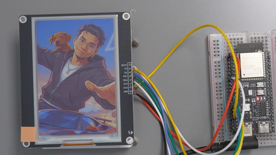
EPD_3in7_Showcase_JD7601folder from GitHub (it is underHandbook/Arduino/ESP32-S3/in the LingShunLAB repository; you can clone the repository or download its ZIP). The main.ino, driver.h/.cpp, andphoto_data.hmust be in this folder, and the folder name must match the main.inofilename. - Wiring: connect BUSY, RST, DC, CS, MOSI, and SCK to GPIO7, 8, 9, 10, 11, and 12 respectively; connect VDD to 3.3 V and share GND with the development board.
- Install esp32 Arduino Core 3.3.10, Adafruit GFX Library 1.13.0, and its dependency Adafruit BusIO 1.17.4.
- Select
ESP32S3 Dev Moduleas the board, compile and upload, then open the Serial Monitor at 115200 baud. HOLD_MSdefaults to 3000 ms. It is the extra wait after each screen finishes refreshing, not the interval between screen changes.
Introduction
I wanted to make an e-paper demo card with an ESP32-S3: show Hello first, then an English class schedule, and finally leave a photo on the display.
The OSPTEK EPD037A02 I have is a 480×720 six-color SPI display. GxEPD2 has no driver for this panel, so I wrote my own panel driver that handles only the JD7601 SPI timing and frame format. Adafruit GFX handles text and graphics. This article provides the wiring, library setup, and complete code for all three screens.
Final Result
The program plays Hello → English class schedule → photo once. It holds the first two screens for 3000 ms after each refresh, then leaves the photo on the display and does not refresh again in loop().
Component Overview
EPD037A02 Six-Color E-Paper Display
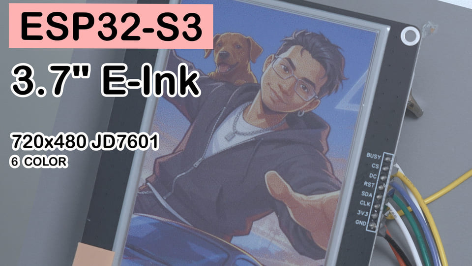
The EPD037A02 is a 3.7-inch six-color e-paper module from OSPTEK. E-paper uses ambient light to show colors and retains its image after power is removed. This example uses it to display text, six color blocks, a class schedule, and a pre-converted photo.
It supports only black, white, yellow, red, blue, and green, with no grayscale. Intermediate colors in a photo must be simulated by mixing pixels of different colors, so you cannot send a JPG directly to the display. It must first be converted to the panel’s frame format.
| Parameter | Specification |
|---|---|
| Model | EPD037A02 |
| Size and resolution | 3.7 inches, 480×720 |
| Colors | Black, white, yellow, red, blue, green |
| Pixel format | 4 bits/pixel, two pixels per byte |
| Interface | 4-wire SPI, 1×8P 2.54 mm pin header |
| Full refresh time | About 15–25 seconds |
| Power supply | 3.3 V |
This display is useful for the demo because one panel can test text, graphics, and six-color photos. The downside is its slow refresh, which makes animation impractical.
Bill of Materials
| Item | Quantity | Notes |
|---|---|---|
| ESP32-S3 development board | 1 | This example uses ESP32S3 Dev Module |
| EPD037A02 module and SPI adapter board | 1 | 480×720 six-color e-paper |
| 2.54 mm jumper wires | 8 | 6 signal wires, 1 power wire, 1 ground wire |
| USB data cable | 1 | Power, uploading, and serial output |
Pin Functions
| Display pin | Direction | Function |
|---|---|---|
| BUSY | Display → ESP32-S3 | High means idle; low means busy |
| CS | ESP32-S3 → Display | Chip select, active low, controlled manually by the program |
| DC | ESP32-S3 → Display | Low for commands; high for data |
| RST | ESP32-S3 → Display | Reset, active low |
| SDA / MOSI | ESP32-S3 → Display | SPI data |
| CLK / SCK | ESP32-S3 → Display | SPI clock |
| VDD | Power | Connect only to 3.3 V |
| GND | Power | Share ground with the development board |
This display only receives data and does not send any back, so MISO is not needed. BS0 on the adapter board is grounded through a 10 kΩ resistor, fixing the module in 4-wire SPI mode. This mode requires DC to distinguish commands from data, so DC cannot be omitted.
Wiring
Disconnect power from the development board before making the connections below.
| Display pin | ESP32-S3 | Purpose |
|---|---|---|
| BUSY | GPIO7 | Read the panel’s busy/idle state |
| CS | GPIO10 | Manual chip select |
| DC | GPIO9 | Distinguish commands from data |
| RST | GPIO8 | Panel reset |
| SDA / MOSI | GPIO11 | SPI data |
| CLK / SCK | GPIO12 | SPI clock |
| VDD | 3.3 V | Module power |
| GND | GND | Common ground |
VDD must be connected to 3.3 V only, never 5 V. Check every wire after connecting them, especially whether SDA and CLK have been swapped.
After wiring:
- Connect the development board over USB, then select
ESP32S3 Dev Moduleand the appropriate port in Arduino IDE. - Open the complete example, compile it, and upload it.
- Open the Serial Monitor and set it to 115200 baud. If you do not see the startup log, press RESET on the development board to run the program again. It plays only once, so opening the monitor late means missing earlier output.
- The serial output should show, in order: frame buffer information, panel initialization complete, two “refresh complete” messages (the photo screen does not print refresh timing), and finally
Done. Last picture stays on screen.. The display should show all three screens in sequence. Both the log and the display must behave as described to confirm that everything works.
Required Libraries
In Arduino IDE’s Boards Manager, search for esp32 and install Espressif Systems’ esp32 Arduino Core. This article uses 3.3.10.
Then search for and install the following libraries in Library Manager. If prompted to install dependencies while installing Adafruit GFX, choose to install all of them so that Adafruit BusIO is installed as well.
| Library | Tested version | Source |
|---|---|---|
| Adafruit GFX Library | 1.13.0 | Adafruit-GFX-Library |
| Adafruit BusIO | 1.17.4 | Adafruit_BusIO |
| SPI | Included with esp32 Core 3.3.10 | Included with arduino-esp32; no separate installation needed |
| EPD037A02_GFX | No version specified | Included with this project; keep it in the same directory as the main .ino rather than copying it to the libraries directory |
Adafruit GFX draws text and graphics. EPD037A02_GFX handles panel initialization, SPI transfers, six-color encoding, and refreshing. Command sets differ between panel models, so this layer cannot simply be replaced with a library for another e-paper display.
Complete Code
The example source is on GitHub. Both the folder and the main program file are named EPD_3in7_Showcase_JD7601; these names must match for Arduino IDE to open the project. The main files are:
EPD_3in7_Showcase_JD7601/
├── EPD_3in7_Showcase_JD7601.ino
├── EPD037A02_GFX.h
├── EPD037A02_GFX.cpp
├── photo_data.h
└── tool/
    ├── epd_photo.py                  # Photo conversion script
    └── 02-driver-dog-car-480x720.png # Original example photo
The code for the first three files is shown below. photo_data.h contains more than ten thousand lines and is not reproduced here. Download it from the repository; the program will not compile without it.
It contains a 172800-byte photo_driver array converted from tool/02-driver-dog-car-480x720.png. It stores the converted panel frame, not the contents of the PNG file.
The code below has the same logic as the repository source; only some comments have been adjusted. The repository is authoritative.
Main Program: EPD_3in7_Showcase_JD7601.ino
/*
 * EPD_3in7_Showcase — Hello + English class schedule + one photo
 * Display: OSPTEK 3.7" E6, 480×720, JD7601
 * Controller: ESP32-S3
 *
 * Beginners only need to edit this file. Use the fonts included with Adafruit GFX; no custom font library is needed.
 * Installation: Search for Adafruit GFX Library in Arduino IDE Library Manager.
 * Opening: Download the entire Showcase folder, then open this .ino; do not copy only the main file.
 */

#include "EPD037A02_GFX.h"
#include "photo_data.h"

// Pin order: CS, DC, RST, BUSY, SCK, MOSI; power must be 3.3V only.
EPD037A02_GFX epd(10, 9, 8, 7, 12, 11);
#define HOLD_MS 3000

// The built-in 5×7 font's y coordinate is at the top of the text; each character occupies 6×8 pixels.
void text(const char *s, int x, int y, uint8_t size, uint8_t color) {
  epd.setFont();                 // Use the built-in GFX font; no separate setFont(font) needed
  epd.setTextSize(size);
  epd.setTextColor(color);
  epd.setCursor(x, y);
  epd.print(s);
}

void textCenter(const char *s, int y, uint8_t size, uint8_t color) {
  int w = strlen(s) * 6 * size;
  text(s, (480 - w) / 2, y, size, color);
}

void drawHello() {
  epd.fillScreen(EPD_WHITE);
  epd.drawRect(0, 0, 480, 720, EPD_BLACK);
  textCenter("HELLO", 65, 9, EPD_BLACK);
  textCenter("WORLD", 150, 9, EPD_RED);
  epd.fillRect(40, 245, 400, 4, EPD_BLACK);

  // The six color blocks also check the six-color mapping and image orientation.
  const uint8_t colors[6] = {
    EPD_BLACK, EPD_WHITE, EPD_YELLOW, EPD_RED, EPD_BLUE, EPD_GREEN
  };
  const char *labels[6] = { "K", "W", "Y", "R", "B", "G" };
  for (int i = 0; i < 6; i++) {
    int x = 16 + i * 76;
    epd.fillRect(x, 295, 68, 110, colors[i]);
    epd.drawRect(x, 295, 68, 110, EPD_BLACK);
    text(labels[i], x + 22, 430, 4, EPD_BLACK);
  }
  textCenter("3.7INCH 480X720", 525, 4, EPD_BLACK);
  textCenter("E6 6-COLOR EPD", 570, 4, EPD_BLACK);
  textCenter("ESP32-S3 OK", 640, 4, EPD_BLUE);
}

// Change only these lines to edit the class schedule.
const char *subjects[6] = {
  "MATH", "CHINESE", "ENGLISH", "PHYSICS", "CHEMISTRY", "STUDY HALL"
};
const char *rooms[6] = {
  "ROOM 302", "ROOM 302", "AUDIO LAB", "PHYS LAB", "CHEM LAB", "ROOM 302"
};
const char *times[6] = { "08:00", "08:55", "NOW", "11:05", "14:00", "14:55" };
const uint8_t bars[6] = {
  EPD_BLUE, EPD_RED, EPD_RED, EPD_BLACK, EPD_YELLOW, EPD_WHITE
};

void drawAgenda() {
  epd.fillScreen(EPD_WHITE);
  epd.fillRect(0, 0, 480, 100, EPD_BLACK);
  text("MON - NOV 9", 24, 20, 4, EPD_WHITE);
  text("WEEK 12 - 6 CLASSES", 24, 65, 2, EPD_YELLOW);

  for (int i = 0; i < 6; i++) {
    int y = 115 + i * 92;
    bool now = (i == 2);
    epd.fillRoundRect(18, y, 444, 80, 5, now ? EPD_RED : EPD_WHITE);
    if (!now) epd.drawRoundRect(18, y, 444, 80, 5, EPD_BLACK);
    if (bars[i] != EPD_WHITE) epd.fillRect(20, y + 2, 9, 76, bars[i]);

    uint8_t fg = now ? EPD_WHITE : EPD_BLACK;
    text(subjects[i], 45, y + 12, 3, fg);
    text(rooms[i], 45, y + 47, 2, fg);
    text(times[i], 365, y + 25, 2, fg);
  }
  text("NEXT 11:05 PHYSICS", 20, 688, 2, EPD_BLACK);
}

bool showScreen(uint8_t index) {
  switch (index) {
    case 0: drawHello();  return epd.display();
    case 1: drawAgenda(); return epd.display();
    case 2: return epd.displayRawFrame(photo_driver, PHOTO_DRIVER_BYTES);
    default: return false;
  }
}

void setup() {
  // Step 1: Open the serial port; it helps identify where the program gets stuck.
  Serial.begin(115200);
  delay(500);
  Serial.println("Showcase: Hello -> English agenda -> portrait");

  // Step 2: Allocate the frame buffer, initialize SPI, then reset and initialize the panel.
  if (!epd.begin()) {
    Serial.println("Init failed: check 3V3, GND, wiring and BUSY.");
    return;
  }

  // Step 3: Play each of the three screens once. Stop on failure instead of refreshing subsequent screens.
  for (uint8_t i = 0; i < 3; i++) {
    if (!showScreen(i)) {
      Serial.println("Refresh failed; stopped. Check wiring and BUSY.");
      return;
    }
    if (i < 2) delay(HOLD_MS);   // This is the hold after refreshing, not the screen-change period
  }
  Serial.println("Done. Last picture stays on screen.");
}

void loop() {
  // Plays only once. Edit subjects / rooms / times above to change the class schedule.
}

// Step 4: Reject photo frames with incorrect dimensions or length at compile time.
static_assert(PHOTO_DRIVER_W == 480 && PHOTO_DRIVER_H == 720,
              "Photo must be 480x720");
static_assert(PHOTO_DRIVER_BYTES == EPD037A02_BUF_BYTES,
              "Photo must be 172800 bytes");
Panel Driver Interface: EPD037A02_GFX.h
/*
 * EPD037A02_GFX — Panel driver class for Adafruit_GFX
 * OSPTEK 3.7" E6 e-paper, 480×720, six colors (JD7601 / IST7601 / IST7163)
 *
 * The panel layer is implemented here, while the graphics layer directly inherits Adafruit_GFX.
 * This makes the existing drawLine, fillCircle, setFont, and print functions available directly.
 *
 * MIT / CC BY 4.0, consistent with the rest of the repository.
 */

#ifndef EPD037A02_GFX_H
#define EPD037A02_GFX_H

#include <Arduino.h>
#include <SPI.h>
#include <Adafruit_GFX.h>

/* ------------------------------ Panel constants ------------------------------- */

#define EPD037A02_WIDTH    480
#define EPD037A02_HEIGHT   720
#define EPD037A02_BUF_BYTES ((size_t)EPD037A02_WIDTH * EPD037A02_HEIGHT / 2) /* 172800 */

// One byte holds two vertically adjacent pixels. If testing shows a 1–2 px offset, change this to 1.
#ifndef EPD037A02_SWAP_NIBBLE
#define EPD037A02_SWAP_NIBBLE 0
#endif

// JD7601 4-bit color values; 0x4 is invalid, so do not assign consecutive values from 0–5.
enum EPDColor : uint8_t {
  EPD_BLACK  = 0x0,
  EPD_WHITE  = 0x1,
  EPD_YELLOW = 0x2,
  EPD_RED    = 0x3,
  EPD_BLUE   = 0x5,
  EPD_GREEN  = 0x6,
};

/* ------------------------------- Driver class -------------------------------- */
/*
 * Usage:
 *   EPD037A02_GFX display(10, 9, 8, 7);    // cs, dc, rst, busy
 *   display.begin();                       // Allocate frame buffer + reset + INIT
 *   display.setRotation(0);                // 0/2 = 480×720, 1/3 = 720×480
 *   display.fillScreen(EPD_WHITE);
 *   display.setFont(&FreeSansBold24pt7b);
 *   display.setCursor(20, 120);  display.print("Hello");
 *   display.display();                     // Push to display + full refresh (15–25 s)
 *
 * Colors are 4-bit indexed values, only six colors, not RGB565.
 * A 16-bit color value also compiles, but only its low 4 bits select a color, so the result is meaningless.
 */
class EPD037A02_GFX : public Adafruit_GFX {
 public:
  EPD037A02_GFX(int8_t cs, int8_t dc, int8_t rst, int8_t busy,
                int8_t sck = -1, int8_t mosi = -1, SPIClass *spi = &SPI);
  ~EPD037A02_GFX();

  // Allocate the frame buffer, initialize GPIO/SPI, and reset and initialize the panel.
  // Returns false if memory is insufficient or BUSY does not respond; the display remains unchanged.
  bool begin(uint32_t spi_hz = 2000000);

  // Push the frame buffer to the display and perform a full refresh. Blocks for 15–25 s; returns false on BUSY timeout.
  bool display();

  // Send a packed 480×720 native frame directly without allocating another photo frame buffer.
  bool displayRawFrame(const uint8_t *frame, size_t bytes);

  // Panel deep sleep. Wake by power cycling, or pull RST and call begin() again.
  bool sleep();

  // Clear only the frame buffer without refreshing immediately. For ghosting on the color display, call clear() then display() to refresh a white screen.
  void clear(uint16_t color = EPD_WHITE);

  // drawPixel is the pure virtual function required by Adafruit_GFX; fillScreen is overridden with memset for speed.
  void drawPixel(int16_t x, int16_t y, uint16_t color) override;
  void fillScreen(uint16_t color) override;

  // Quantize RGB to the nearest of the six colors; useful for simple images.
  static uint8_t fromRGB(uint8_t r, uint8_t g, uint8_t b);

  uint8_t *buffer() const { return _buf; }
  bool ready() const { return _buf != nullptr; }
  uint32_t lastRefreshMs() const { return _lastRefreshMs; }
  void setVerbose(bool v) { _verbose = v; }

 private:
  int8_t _cs, _dc, _rst, _busy, _sck, _mosi;
  SPIClass *_spi;
  uint32_t _spiHz;
  uint8_t *_buf;
  uint32_t _lastRefreshMs;
  bool _verbose;

  void _alloc();
  void _spiSend(const uint8_t *buf, size_t len);
  void _cmd(uint8_t c);
  void _data(uint8_t d);
  void _dataBuf(const uint8_t *buf, size_t len);
  bool _waitBusy(const char *what, uint32_t timeout_ms = 60000);
  bool _reset();
  bool _initPanel();
};

#endif /* EPD037A02_GFX_H */
Panel Driver Implementation: EPD037A02_GFX.cpp
/*
 * EPD037A02_GFX.cpp — Panel layer: SPI, timing, frame format
 * This layer does only three things: send bytes, wait for BUSY, and convert (x,y) to a frame buffer index.
 * Adafruit_GFX handles graphics, fonts, and rotation.
 */

#include "EPD037A02_GFX.h"

#include <string.h>
#include <pgmspace.h>

#if defined(ESP32)
#include <esp32-hal-psram.h>
#endif

namespace {
// Two pixels per byte, so one 720-pixel vertical column occupies 360 bytes.
const size_t kColBytes  = EPD037A02_HEIGHT / 2;
const size_t kChunk     = 2048;    // Maximum size of one SPI transfer, consistent with the vendor example
const uint32_t kBusyTmo = 60000;   // Full refresh takes up to 25 s; this leaves headroom
}  // namespace

EPD037A02_GFX::EPD037A02_GFX(int8_t cs, int8_t dc, int8_t rst, int8_t busy,
                             int8_t sck, int8_t mosi, SPIClass *spi)
    : Adafruit_GFX(EPD037A02_WIDTH, EPD037A02_HEIGHT),
      _cs(cs), _dc(dc), _rst(rst), _busy(busy), _sck(sck), _mosi(mosi),
      _spi(spi), _spiHz(2000000), _buf(nullptr), _lastRefreshMs(0),
      _verbose(true) {}

EPD037A02_GFX::~EPD037A02_GFX() {
  if (_buf) {
    free(_buf);   // Memory allocated with ps_malloc is also released with free()
    _buf = nullptr;
  }
}

/* ============================ Memory / initialization ============================ */

void EPD037A02_GFX::_alloc() {
  if (_buf) return;
#if defined(ESP32)
  if (psramFound()) _buf = (uint8_t *)ps_malloc(EPD037A02_BUF_BYTES);
#endif
  if (!_buf) _buf = (uint8_t *)malloc(EPD037A02_BUF_BYTES);
}

bool EPD037A02_GFX::begin(uint32_t spi_hz) {
  // Step 1: Obtain the 172800-byte frame buffer and fill it with white first.
  _spiHz = spi_hz;
  _alloc();
  if (!_buf) {
    if (_verbose) {
      Serial.printf("[EPD] Frame buffer allocation failed; %u bytes required\n",
                    (unsigned)EPD037A02_BUF_BYTES);
    }
    return false;
  }

  // malloc does not zero memory; fill with white first to avoid sending uninitialized memory to the display.
  clear(EPD_WHITE);

  // Step 2: Configure the pins. CS is controlled manually; MISO is not connected.
  pinMode(_cs, OUTPUT);   digitalWrite(_cs, HIGH);
  pinMode(_dc, OUTPUT);   digitalWrite(_dc, HIGH);
  pinMode(_rst, OUTPUT);  digitalWrite(_rst, HIGH);
  pinMode(_busy, INPUT);

  // Parameter order is SCK, MISO, MOSI, SS. Pass -1 for SS; do not give CS control to the peripheral.
  _spi->begin(_sck, -1, _mosi, -1);

  if (_verbose) {
    Serial.printf("[EPD] Frame buffer %u B, SPI %lu Hz\n",
                  (unsigned)EPD037A02_BUF_BYTES, (unsigned long)_spiHz);
  }

  // Step 3: Reset the panel and send initialization commands.
  return _initPanel();
}

bool EPD037A02_GFX::_initPanel() {
  if (!_reset()) return false;

  _cmd(0xE9); _data(0x01);   // Vendor INIT: JD7601 initialization command

  if (_verbose) Serial.println("[EPD] Panel initialization complete");
  return true;
}

/* ============================== Low-level SPI =============================== */

void EPD037A02_GFX::_spiSend(const uint8_t *buf, size_t len) {
  digitalWrite(_cs, LOW);
  _spi->beginTransaction(SPISettings(_spiHz, MSBFIRST, SPI_MODE0));
  _spi->writeBytes(buf, len);
  _spi->endTransaction();
  digitalWrite(_cs, HIGH);
}

void EPD037A02_GFX::_cmd(uint8_t c) {
  digitalWrite(_dc, LOW);    // DC=L: command
  _spiSend(&c, 1);
}

void EPD037A02_GFX::_data(uint8_t d) {
  digitalWrite(_dc, HIGH);   // DC=H: data
  _spiSend(&d, 1);
}

void EPD037A02_GFX::_dataBuf(const uint8_t *buf, size_t len) {
  digitalWrite(_dc, HIGH);
  while (len) {
    size_t n = (len > kChunk) ? kChunk : len;
    _spiSend(buf, n);
    buf += n;
    len -= n;
  }
}

// BUSY high = idle, low = busy. The main text of datasheet Note 6-4 states the reverse; follow the pin table and actual measurements.
bool EPD037A02_GFX::_waitBusy(const char *what, uint32_t timeout_ms) {
  uint32_t t0 = millis();
  while (digitalRead(_busy) == LOW) {
    if (millis() - t0 > timeout_ms) {
      if (_verbose) Serial.printf("[EPD] BUSY timeout: %s\n", what);
      return false;
    }
    delay(2);
  }
  return true;
}

// Vendor RESET timing: low 20 → high 10 → low 20 → high 10 ms, then wait for BUSY.
bool EPD037A02_GFX::_reset() {
  digitalWrite(_rst, LOW);  delay(20);
  digitalWrite(_rst, HIGH); delay(10);
  digitalWrite(_rst, LOW);  delay(20);
  digitalWrite(_rst, HIGH); delay(10);

  if (digitalRead(_busy) == LOW) {
    if (_verbose) Serial.println("[EPD] Waiting for BUSY to go high (up to 10 s); on timeout, check 3V3 / GND / ribbon cable");
    if (!_waitBusy("reset", 10000)) return false;
  }
  delay(10);
  return true;
}

/* ============================== Refresh sequence =============================== */

bool EPD037A02_GFX::display() {
  if (!_buf) return false;
  uint32_t t0 = millis();

  _cmd(0x10);                             // DTM: prepare to write RAM
  if (!_waitBusy("DTM")) return false;
  _dataBuf(_buf, EPD037A02_BUF_BYTES);

  _cmd(0x04);                             // PON: turn on high voltage
  if (!_waitBusy("PON")) return false;
  delay(10);

  _cmd(0x12); _data(0x00);                // DRF: start refresh
  delay(10);
  if (!_waitBusy("DRF", kBusyTmo)) return false;

  _cmd(0x02); _data(0x00);                // POF: turn off high voltage
  if (!_waitBusy("POF")) return false;
  delay(20);

  _lastRefreshMs = millis() - t0;
  if (_verbose) Serial.printf("[EPD] Refresh complete %lu ms\n", (unsigned long)_lastRefreshMs);
  return true;
}

bool EPD037A02_GFX::displayRawFrame(const uint8_t *frame, size_t bytes) {
  if (!frame || bytes != EPD037A02_BUF_BYTES) return false;

  _cmd(0x10);
  if (!_waitBusy("DTM")) return false;

  // Copy 2048 bytes at a time from Flash to RAM, then send over SPI; do not let DMA read Flash directly.
  uint8_t chunk[kChunk];
  digitalWrite(_dc, HIGH);
  for (size_t off = 0; off < bytes; off += sizeof(chunk)) {
    size_t n = bytes - off;
    if (n > sizeof(chunk)) n = sizeof(chunk);
    memcpy_P(chunk, frame + off, n);
    _spiSend(chunk, n);
  }

  _cmd(0x04);
  if (!_waitBusy("PON")) return false;
  delay(10);
  _cmd(0x12); _data(0x00);
  delay(10);
  if (!_waitBusy("DRF", kBusyTmo)) return false;
  _cmd(0x02); _data(0x00);
  if (!_waitBusy("POF")) return false;
  delay(20);
  return true;
}

bool EPD037A02_GFX::sleep() {
  _cmd(0x07); _data(0xA5);
  if (_verbose) Serial.println("[EPD] Entered deep sleep");
  return true;
}

/* ================================ Drawing ================================= */

void EPD037A02_GFX::clear(uint16_t color) {
  if (!_buf) return;
  uint8_t c = (uint8_t)(color & 0x0F);
  memset(_buf, (int)((c << 4) | c), EPD037A02_BUF_BYTES);
}

void EPD037A02_GFX::fillScreen(uint16_t color) { clear(color); }

void EPD037A02_GFX::drawPixel(int16_t x, int16_t y, uint16_t color) {
  if (!_buf) return;
  if (x < 0 || y < 0 || x >= _width || y >= _height) return;

  // First convert the rotation-dependent logical coordinates to the panel's native coordinates.
  int16_t dx, dy;
  switch (rotation & 3) {
    case 0:  dx = x;                 dy = y;                 break;
    case 1:  dx = WIDTH - 1 - y;     dy = x;                 break;
    case 2:  dx = WIDTH - 1 - x;     dy = HEIGHT - 1 - y;    break;
    default: dx = y;                 dy = HEIGHT - 1 - x;    break;
  }

  // The panel packs data by vertical columns and scans each column from bottom to top, so a Y mirror is also required.
  // Writing in the usual horizontal row-major order rotates the image by 90° and produces shifted repetitions.
  const int16_t fy = HEIGHT - 1 - dy;
  size_t i = (size_t)dx * kColBytes + (size_t)(fy >> 1);

#if EPD037A02_SWAP_NIBBLE
  const bool lowNibble = ((fy & 1) == 0);
#else
  const bool lowNibble = ((fy & 1) != 0);
#endif

  // Split one byte into two nibbles and modify only the half containing the target pixel.
  const uint8_t c = (uint8_t)(color & 0x0F);
  if (lowNibble) _buf[i] = (uint8_t)((_buf[i] & 0xF0) | c);
  else           _buf[i] = (uint8_t)((_buf[i] & 0x0F) | (c << 4));
}

/* ============================ RGB → six-color quantization =========================== */

struct EPDRgbRef { uint8_t r, g, b, code; };

// Reference colors use typical Spectra 6 / E6 appearance; slightly darker values better match what the eye sees.
static const EPDRgbRef kRefs[6] = {
    {  0,   0,   0, EPD_BLACK  },
    {255, 255, 255, EPD_WHITE  },
    {255, 232,   0, EPD_YELLOW },
    {190,  30,  45, EPD_RED    },
    { 35,  70, 150, EPD_BLUE   },
    { 40, 110,  60, EPD_GREEN  },
};

uint8_t EPD037A02_GFX::fromRGB(uint8_t r, uint8_t g, uint8_t b) {
  // Weighted Euclidean distance, with a higher weight for green.
  int32_t best = INT32_MAX;
  uint8_t code = EPD_BLACK;
  for (int k = 0; k < 6; k++) {
    int32_t dr = (int32_t)r - kRefs[k].r;
    int32_t dg = (int32_t)g - kRefs[k].g;
    int32_t db = (int32_t)b - kRefs[k].b;
    int32_t d = 2 * dr * dr + 4 * dg * dg + 3 * db * db;
    if (d < best) { best = d; code = kRefs[k].code; }
  }
  return code;
}
Code Explanation
How pixels are stored. drawPixel() is the easiest function to get wrong. The display is 480×720 at 4 bits per pixel, so one frame is 480×720÷2 = 172800 bytes.
Unlike ordinary displays that accept data by rows, this panel receives it in vertical columns: 480 columns of 360 bytes each, with each column scanned from bottom to top. The code therefore applies a Y mirror first, fy = HEIGHT-1-dy, then calculates the byte position with i = dx*360 + (fy>>1).
Color encoding. The six color codes are not consecutive: black, white, yellow, and red are 0x0–0x3, while blue and green are 0x5 and 0x6; 0x4 is invalid. Use enumerations such as EPD_BLACK when drawing instead of entering your own sequence numbers.
How the three screens refresh. The for loop in setup() runs three times. The first two screens are drawn into the frame buffer, then display() pushes and refreshes them. The third screen calls displayRawFrame(), which copies data from photo_data.h in 2048-byte blocks from Flash to RAM before sending it over SPI.
Memory. The photo screen does not use the frame buffer, but the first two screens do, so the program always needs a 172800-byte frame buffer. It uses PSRAM preferentially when available; otherwise, or if allocation fails, it uses internal RAM.
Hold time. Each screen takes 15–25 seconds to refresh. HOLD_MS is only the extra wait after a refresh finishes, so the actual interval between the first two screens is the refresh time plus 3 seconds. The program does not loop; press RESET to restart the demo.
Changing the class schedule. Edit the three arrays subjects, rooms, and times; their six rows correspond one-to-one. bars sets the color of the bar at the left of each row. The highlighted “current class” is fixed at row 3 (i == 2). The title date, WEEK 12, and NEXT 11:05 PHYSICS at the bottom are hard-coded text. The example does not read a clock and does not update automatically.
Converting a Photo to Panel Data
The photo is not processed on the development board. A computer first converts it into a six-color bitmap, and the ESP32-S3 only sends the converted data to the display.
JPG/PNG → Center-crop and resize to 480×720
→ Adjust exposure, contrast, and saturation → Six-color dithering → Convert to panel color values
→ Arrange in vertical columns, apply a Y mirror, and pack two pixels into one byte
→ 172800-byte array (photo_data.h) → Compile into Flash
→ ESP32-S3 sends it to the display over SPI
Dithering interleaves pixels of different colors so that the eye perceives a field of dots as an intermediate color. It does not add colors; after conversion, every pixel is still only black, white, yellow, red, blue, or green. The conversion script calculates color distances using the colors as they actually appear on e-paper (slightly darker), but outputs panel color values.
The earlier sections “How pixels are stored” and “Color encoding” explain the pixel arrangement and color encoding, and the script packs data using the same rules. The generated data can therefore be sent directly to the panel; the development board does not need to decode a JPG or calculate dithering.
Changing the Photo
Back up the original photo_data.h first, because the command below overwrites it. The computer needs Python 3, Pillow, and numpy (pip install pillow numpy). They are not needed just to run the example.
Run this in the example folder:
cd EPD_3in7_Showcase_JD7601
python3 tool/epd_photo.py my-photo.jpg --header photo_data.h --header-name photo_driver- The array name must remain
photo_driver. The script uses it to generatePHOTO_DRIVER_W,PHOTO_DRIVER_H, andPHOTO_DRIVER_BYTES, which are used by thestatic_assertstatements at the end of the main program. - By default, the image is center-cropped to 480×720. To avoid cutting off the edges, add
--fit contain(letterboxing) or--fit stretch(stretching and distortion). - The output is always 480×720 and 172800 bytes. After generating it, simply recompile and upload; no filesystem upload is needed.
Troubleshooting
Compilation Error: undefined reference to EPD037A02_GFX
Symptom: Functions such as begin() and display() cannot be found during linking.
Cause: EPD037A02_GFX.cpp was not compiled. Arduino compiles .cpp files only in the sketch root and the src/ subdirectory, not those in other subdirectories such as driver/.
Fix: Put the main .ino, driver .h, and .cpp in the same directory, reopen the example, and compile again.
No Output in the Serial Monitor
Symptom: The upload completes, but the serial monitor is blank.
Cause: The baud rate is incorrect; USB CDC is not enabled when using the onboard USB port; or the monitor was opened too late, after the program had already finished its output.
Fix: Set the baud rate to 115200 and confirm that the correct port is selected. When using the onboard USB port, set USB CDC On Boot to Enabled in Arduino IDE and upload again. You can also use the UART port instead, following the board’s instructions. Finally, press RESET to run the program again.
Serial Output Appears, but the Display Stays Completely White
Symptom: The program is running, but no image appears on the display.
Cause: SDA and CLK are commonly swapped, CS or DC is wired incorrectly, or ground is not shared.
Fix: Disconnect power and check all 8 wires individually. Measure whether VDD is 3.3 V, then check GND continuity. Also, the fourth argument to SPI.begin() in the driver must be -1; _spiSend() controls CS manually by pulling it low and high.
Serial Monitor Reports a BUSY Timeout During reset
Symptom: The log stops at “Waiting for BUSY to go high,” then reports a reset timeout and finally prints Init failed.
Cause: BUSY remains low. The display may be unpowered, BUSY may be wired incorrectly or loosely, or the ribbon cable may have poor contact.
Fix: Confirm that VDD is connected to 3.3 V, the ribbon cable is fully inserted, and BUSY is connected to GPIO7. Check these before changing any refresh code. After fixing the issue, power cycle and upload again.
Timeout During DRF, or Part of the Image Is Corrupted
Symptom: Initialization succeeds, but a timeout occurs during refresh, or part of the image is abnormal.
Common causes: Insufficient supply current, jumper wires that are too long, or an SPI clock that is too fast.
Fix: Shorten the jumper wires, check the ground connection, and use a USB port or power supply with stable output. Keep the SPI speed at the default 2 MHz. If you changed the argument to epd.begin(), remove it to restore the default.
Image Rotated 90° and Repeated in About Three Segments
Symptom: Text and color blocks are recognizable, but their orientation is wrong and they repeat with an offset.
Cause: The frame data is arranged by rows, while the panel actually receives it in vertical columns. This should not happen with the driver in this article; it is more common after modifying the driver yourself or using an old driver version.
Fix: Verify that drawPixel() contains size_t i = (size_t)dx * kColBytes + (size_t)(fy >> 1); and that kColBytes = EPD037A02_HEIGHT / 2, which is 360.
Image Is Not Repeated, but Is Upside Down
Symptom: The letter order is correct, but the whole image is vertically flipped.
Cause: The panel scans each column from bottom to top, and the code is missing the Y mirror.
Fix: Verify that drawPixel() contains const int16_t fy = HEIGHT - 1 - dy; and that subsequent address and nibble calculations use fy. Do not simply reverse the byte order.
Thin Lines Are Offset and Strokes Look Like Comb Teeth
Symptom: The overall position is correct, but adjacent pixels are offset by 1–2 px.
Cause: The order of the high and low nibbles within a byte may be reversed.
Fix: Change EPD037A02_SWAP_NIBBLE in EPD037A02_GFX.h from 0 to 1. This swaps only the order of the two pixels within a byte; it does not mirror the whole image.
Compilation Error: Photo must be 480x720 or Photo must be 172800 bytes
Symptom: One of the two static_assert statements is triggered.
Cause: The replacement photo_data.h is not 480×720, or the frame length is not 172800 bytes.
Fix: Regenerate it with the conversion command above, keeping --header-name photo_driver. Then check that PHOTO_DRIVER_W, PHOTO_DRIVER_H, and PHOTO_DRIVER_BYTES are 480, 720, and 172800 respectively.
FAQ
Can I use different pins for the EPD037A02?
Yes. Update both the wiring and EPD037A02_GFX epd(10, 9, 8, 7, 12, 11). The argument order is CS, DC, RST, BUSY, SCK, MOSI. On ESP32-S3, avoid GPIO0, 45, and 46 (boot-related), GPIO19 and 20 (USB), and GPIO26–37 (used by Flash/PSRAM); also check your own development board’s schematic. I have compiled only with GPIO7–12 and have not tested other pins.
What is the SPI speed? Can it be changed to 8 MHz?
This example defaults to 2 MHz, Mode 0, MSB first. To increase it, change the argument to epd.begin(), for example epd.begin(4000000). Start testing at 4 MHz; return to 2 MHz if noise or image corruption appears. I have not tested 8 MHz with this three-screen example.
Can it run on 5 V? How much current does it draw while refreshing?
No. VDD must be connected only to 3.3 V, and GND must be shared with the development board. The boost circuit’s load increases during refresh, so keep jumper wires short and the power supply stable. I have not measured the peak refresh current and will not provide an estimate here.
How much RAM and Flash does it use? Will it max out the CPU?
This build uses 525724 bytes of Flash (40%) and 23576 bytes for global variables (7%). At runtime, it also allocates a 172800-byte frame buffer and uses a 2048-byte temporary buffer when sending the photo. Refreshing is blocking, so loop() cannot do anything else during a refresh; do not schedule tasks that require strict timing. I have not measured CPU utilization.
Can I use GxEPD2 or a regular ESP32?
The GxEPD2 1.6.9 version I checked has no driver class for this 480×720 JD7601 six-color panel, so it cannot be used directly. A regular ESP32 should be portable in theory, but the SPI and PSRAM platform code would need changes, and you would need to confirm that its RAM can hold the 172800-byte frame buffer. I have not tested other controllers.
The display shows nothing at all. Which wires should I check first?
First measure whether VDD is 3.3 V, then check GND, BUSY, CS, DC, SDA, and CLK. Set the serial monitor to 115200. For a reset or DRF timeout, follow the corresponding section above. If there is no serial output at all, check the port and USB CDC settings first rather than changing the frame format.
Can it display Chinese or a JPG directly?
No. The interface uses GFX’s built-in 5×7 font, and all example text is English; no Chinese font library is included. A JPG cannot be sent directly either. It must first be converted to a 480×720, 172800-byte panel frame. The included photo_data.h is already converted; see “Changing the Photo” above to use a different image.
Why does it stop after playing once? Does the photo remain after power is removed?
The example is designed to play only once. loop() is empty, and the photo remains on the display. E-paper retains its image after power is removed. Press RESET to replay it; to loop automatically, you need to add your own trigger logic. I have not tested intervals for continuous rotation.
Further Ideas
- Replace the hard-coded class schedule with serial input, then connect real data after confirming the layout.
- Add a button to switch manually between Hello, the class schedule, and the photo.
- Add an RTC so the title date and “current class” update automatically.
- Store multiple photos in LittleFS or on an SD card to make a button-controlled digital photo frame.
References
-
Example source for this article (GitHub): Complete files for the three-screen example and the photo conversion script.
-
Espressif ESP32-S3 official product page: Controller chip information.
-
Espressif ESP32-S3 official datasheet: GPIO, SPI, and electrical specifications.
-
Adafruit GFX Library GitHub: Text and graphics interfaces.
-
Adafruit BusIO GitHub: Dependency library for Adafruit GFX.
-
esp32 Arduino Core GitHub: Arduino core and SPI support.
-
Adafruit GFX font guide: Using built-in fonts and FreeFont.
-
Vendor open-source materials and examples: Datasheet, schematic, and vendor examples.