ESP32-S3 + ADXL335 3-Axis Accelerometer Dashboard on a JD9855 Round Display | Why Shaking Reacts More Than Tilting
Drive a JD9855 QSPI round display with an ESP32-S3 + ADXL335 (GY-61) to build a real-time 3-axis accelerometer dashboard. Includes wiring diagram, complete Arduino code, troubleshooting, and a clear explanation of the physics behind why shaking is more visible than tilting.
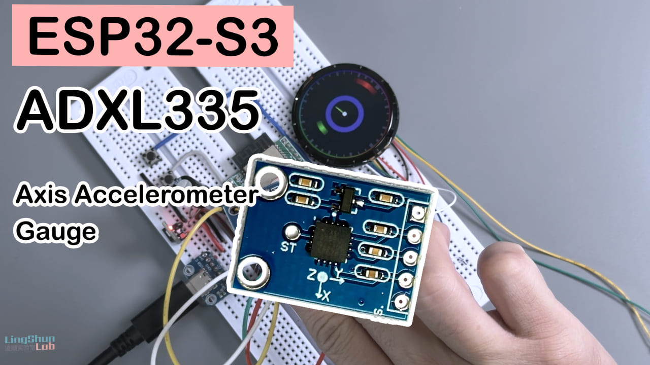
Difficulty: 2/5 (manageable with basic Arduino experience) Estimated time: 30-40 minutes (including calibration and debugging) Test environment: Arduino IDE 2.3.8 · ESP32 Arduino Core 3.3.10
TL;DR (quick start):
- Wire up the display (6-line QSPI) and the ADXL335 (three analog inputs for X/Y/Z) according to the wiring table.
- GPIO5 / GPIO9 / GPIO10 all fall within the ADC1 range of the ESP32-S3, so you don’t have to worry about contention with Wi-Fi.
- After powering on, keep the device flat and still so the program can automatically sample and calibrate the zero point (about 1 second).
- Slowly tilt or forcefully shake the device and watch the three colored rings and the center pointer react on the round display.
Foreword
After two days of fiddling, I pushed the ADXL335’s three-axis data in real time onto a 360x360 round display. When I tilted the device slowly, the pointer barely moved; the moment I gave it a flick or a hard shake, the pointer swung out across most of the dial. At first I assumed my calibration was off, but after digging through some references it clicked - this thing, by its physical nature, isn’t a pure “tilt sensor.” It measures acceleration, and the harder you shake it, the more exaggerated the reading gets. That’s by design, not a bug. I also noticed that my hand-soldered ESP32-S3 dev board has a weak power supply - when the sensor kicks in, the screen visibly dims for a moment. Looks like it’s time to upgrade my ESP32-S3 dev board.
So beyond the complete wiring, code, and gotchas, this article also tries to explain clearly why “shaking is more visible than tilting,” so you don’t end up questioning your sanity in the same trap when you reproduce it.
Result
This 360x360 round display shows the ADXL335’s three-axis acceleration data in real time (note: acceleration, not pure attitude angle). The outer red/green/blue rings correspond to the X / Y / Z axes respectively, and the colored pointer in the center points in the direction of the current resultant force. The harder you shake, the more exaggerated the pointer’s swing. There’s also a breathing-light ring around the edge for decoration.
Component overview
The ESP32-S3 dev board needs no introduction - if you’re reading this, you’ve used an ESP32. Below I’ll only cover the other two core components.
ADXL335 accelerometer (GY-61 module)
What the ADXL335 does is a bit like a bathroom scale - it doesn’t know whether you’re “standing straight,” it only knows how much force is currently acting on it, and it breaks that force down into X/Y/Z components for you. It’s an analog-output three-axis MEMS accelerometer that converts the resultant force on the device (the gravity component plus motion-induced acceleration) into three voltage signals.
| Parameter | Value |
|---|---|
| Type | 3-axis analog-output MEMS accelerometer |
| Range | +/-3.6g (typical) / +/-3g (guaranteed minimum) |
| Sensitivity | 300 mV/g (typical at VS = 3V, proportional to supply) |
| Operating voltage | 1.8V ~ 3.6V |
| Bandwidth (GY-61 module default) | ~50Hz (set by the onboard 0.1uF filter capacitor) |
| Noise density | X/Y ~270 ug/sqrtHz, Z ~550 ug/sqrtHz (Z is about 2x of X/Y) |
The reason to use it is simple: it’s cheap, the analog output wiring is straightforward, and any ADC pin can read it. It’s perfect for visualization-style toy projects, and as long as you’re not after professional-grade attitude estimation, it’s more than enough.
Pinout
ADXL335 (GY-61)
| Module pin | Description |
|---|---|
| VCC / GND | 3.3V supply |
| X / Y / Z | Three analog outputs, connect to ADC pins |
| ST | Self-test pin, usually left unconnected |
TK015F5785 round display (JD9855 driver, QSPI interface)
You can think of this display as “a canvas that only understands signals on four data lines.” The JD9855 is the driver IC that shuttles the color data sent by the MCU to every pixel on the screen; the QSPI (four-wire serial) interface uses fewer pins to achieve a higher refresh rate. It’s a roughly 1.5-inch circular TFT with 360x360 resolution, driven by five signal lines (SCLK / D0-D3 / CS) plus power - no separate DC (data/command) pin is needed.
| Parameter | Value |
|---|---|
| Size | 1.5-inch circular IPS |
| Resolution | 360 x 360 |
| Driver IC | JD9855 |
| Interface | QSPI (4-wire) |
| Supply | 3.3V |
| Brightness / contrast | Per the seller’s spec sheet (may vary between batches) |
The reason I picked it is equally direct: a round display is naturally great-looking for dashboard-style visualizations, the QSPI interface only uses 5 GPIOs (fewer than a traditional parallel interface), and the ESP32-S3’s DMA can drive it comfortably.
Pinout
Display TK015F5785 (JD9855 QSPI)
| Display pin | Description |
|---|---|
| SCLK | QSPI clock |
| D0 ~ D3 | QSPI 4-wire data |
| CS | Chip select |
| VCC / GND | 3.3V supply |
BOM
| Component | Model / specs | Qty | Reference price | Purpose |
|---|---|---|---|---|
| MCU board | ESP32-S3 dev board | 1 | ~30-50 CNY | Main controller + Wi-Fi/Bluetooth reserved |
| Round display | TK015F5785 (JD9855, 360x360, QSPI) | 1 | Varies by seller | Display |
| Accelerometer | ADXL335 (GY-61 module) | 1 | ~8-15 CNY | Capture 3-axis acceleration |
| Dupont wires | Female-to-female | Several | - | Wiring |
Wiring
Display -> ESP32-S3
| Display pin | ESP32-S3 pin |
|---|---|
| SCLK | GPIO6 |
| D0 | GPIO15 |
| D1 | GPIO7 |
| D2 | GPIO11 |
| D3 | GPIO12 |
| CS | GPIO16 |
| VCC | 3.3V |
| GND | GND |
ADXL335 -> ESP32-S3
| Module pin | ESP32-S3 pin |
|---|---|
| VCC | 3.3V |
| GND | GND |
| X | GPIO5 (ADC1) |
| Y | GPIO9 (ADC1) |
| Z | GPIO10 (ADC1) |
After wiring, double-check each connection one by one - this saves 80% of debugging time, especially the four D0~D3 lines on the display. Get one backwards and the screen will most likely garble or stay dark.
Required libraries
You don’t need to install any third-party libraries. The display driver is a hand-written QSPI driver that calls ESP-IDF’s built-in esp_lcd_panel_io and driver/spi_master interfaces directly - nothing to search for in the Library Manager.
The only thing to watch out for is versions:
- Arduino IDE: 2.3.8 (tested OK)
- ESP32 board support package (esp32 by Espressif Systems): 3.3.10 (based on ESP-IDF 5.x) - must be v3.x, because the
quad_modeflag and some DMA interfaces used by the code aren’t necessarily complete on the older v2.x core - Board selection: ESP32S3 Dev Module, USB CDC On Boot set to Enabled
Code
/*
 * =============================================================================
 *  ADXL335 + TK015F5785 round display - 3-axis accelerometer dashboard
 *  =====================================================================
 *
 *  Single scene: 3-axis accelerometer dashboard - real-time display of
 *  three-axis data + resultant force direction, with a center pointer
 *  pointing in the direction of the resultant force.
 *
 *  Hardware: ESP32-S3 + TK015F5785 (JD9855 QSPI) + ADXL335 (GY-61)
 *
 *  +---------------------------------------------------------------------+
 *  |                          Wiring                                     |
 *  +-----------------------------------------------------------+---------+
 *  |  [Display TK015F5785]           |  [ADXL335 (GY-61)]         |
 *  |  SCLK  -> GPIO6                 |  VCC -> 3.3V               |
 *  |  D0    -> GPIO15                |  GND -> GND                |
 *  |  D1    -> GPIO7                 |  X   -> GPIO5 (ADC)        |
 *  |  D2    -> GPIO11                |  Y   -> GPIO9 (ADC)        |
 *  |  D3    -> GPIO12                |  Z   -> GPIO10 (ADC)       |
 *  |  CS    -> GPIO16                |                            |
 *  |  VCC   -> 3.3V                  |                            |
 *  |  GND   -> GND                   |                            |
 *  +-----------------------------------------------------------+---------+
 *
 *  Dependencies: only the esp32 board core v3.x in Arduino IDE
 *  Upload: Board=ESP32S3 Dev Module, USB CDC On Boot=Enabled
 * =============================================================================
 */

#include <Arduino.h>
#include <math.h>
#include <initializer_list>
#include "driver/spi_master.h"
#include "esp_lcd_panel_io.h"
#include "esp_heap_caps.h"

#ifndef M_PI
#define M_PI 3.14159265358979323846
#endif

/* ----------------------------- Pin config ----------------------------- */
// Display pins
#define PIN_LCD_SCLK   6
#define PIN_LCD_D0     15
#define PIN_LCD_D1     7
#define PIN_LCD_D2     11
#define PIN_LCD_D3     12
#define PIN_LCD_CS     16
#define PIN_LCD_BL     -1

// ADXL335 pins (analog inputs)
#define PIN_ACCEL_X    5
#define PIN_ACCEL_Y    9
#define PIN_ACCEL_Z    10

/* =====================================================================
 *  JD9855 QSPI display driver class
 * ===================================================================== */
#define JD9855_SWRESET 0x01
#define JD9855_CASET   0x2A
#define JD9855_RASET   0x2B
#define JD9855_RAMWR   0x2C
#define JD9855_MADCTL  0x36
#define JD9855_COLMOD  0x3A
#define JD9855_SLPOUT  0x11
#define JD9855_DISPON  0x29

class JD9855_QSPI {
public:
    static constexpr int H_RES = 360;
    static constexpr int V_RES = 360;

    static uint16_t color565(uint8_t r, uint8_t g, uint8_t b) {
        return ((uint16_t)(r & 0xF8) << 8) | ((uint16_t)(g & 0xFC) << 3) | (b >> 3);
    }

    bool begin(int sclk, int d0, int d1, int d2, int d3, int cs, int backlight = -1) {
        if (backlight >= 0) { pinMode(backlight, OUTPUT); digitalWrite(backlight, HIGH); }

        spi_bus_config_t buscfg = {};
        buscfg.sclk_io_num  = sclk;
        buscfg.data0_io_num = d0;
        buscfg.data1_io_num = d1;
        buscfg.data2_io_num = d2;
        buscfg.data3_io_num = d3;
        buscfg.max_transfer_sz = H_RES * V_RES * 2;
        esp_err_t ret = spi_bus_initialize(SPI2_HOST, &buscfg, SPI_DMA_CH_AUTO);
        if (ret != ESP_OK) { log_e("spi_bus_initialize: %s", esp_err_to_name(ret)); return false; }

        esp_lcd_panel_io_spi_config_t io_config = {};
        io_config.cs_gpio_num        = cs;
        io_config.dc_gpio_num        = -1;
        io_config.spi_mode           = 3;
        io_config.pclk_hz            = 20 * 1000 * 1000;  // 40MHz is unreliable with long wiring, fall back to 20MHz for stability
        io_config.trans_queue_depth  = 10;
        io_config.lcd_cmd_bits       = 32;
        io_config.lcd_param_bits     = 8;
        io_config.flags.quad_mode    = true;
        ret = esp_lcd_new_panel_io_spi(SPI2_HOST, &io_config, &io);
        if (ret != ESP_OK) { log_e("esp_lcd_new_panel_io_spi: %s", esp_err_to_name(ret)); return false; }

        sendCmd(JD9855_SWRESET);
        delay(20);
        sendInitCommands();
        return true;
    }

    void pushRect(int x, int y, int w, int h, const uint16_t *data) {
        if (w <= 0 || h <= 0) return;
        setAddrWindow(x, y, x + w - 1, y + h - 1);
        size_t n = (size_t)w * h;
        ensureDmaBuf(n * 2);
        for (size_t i = 0; i < n; i++) {
            uint16_t c = data[i];
            dma_buf[i * 2]     = c >> 8;
            dma_buf[i * 2 + 1] = c & 0xFF;
        }
        sendColor(JD9855_RAMWR, dma_buf, n * 2);
    }

    void fillScreen(uint16_t color) {
        uint8_t hi = color >> 8, lo = color & 0xFF;
        const int BUF_PIX = H_RES;
        ensureDmaBuf(BUF_PIX * 2);
        for (int i = 0; i < BUF_PIX; i++) { dma_buf[i*2] = hi; dma_buf[i*2+1] = lo; }
        for (int y = 0; y < V_RES; y++) {
            setAddrWindow(0, y, H_RES - 1, y);
            sendColor(JD9855_RAMWR, dma_buf, BUF_PIX * 2);
        }
    }

private:
    esp_lcd_panel_io_handle_t io = nullptr;
    uint8_t *dma_buf = nullptr;
    size_t   dma_buf_size = 0;

    void ensureDmaBuf(size_t need) {
        if (dma_buf_size >= need) return;
        if (dma_buf) free(dma_buf);
        dma_buf = (uint8_t *)heap_caps_malloc(need, MALLOC_CAP_DMA);
        if (!dma_buf) dma_buf = (uint8_t *)heap_caps_malloc(need, MALLOC_CAP_8BIT);
        dma_buf_size = need;
    }

    void setAddrWindow(int x0, int y0, int x1, int y1) {
        uint8_t caset[4] = { (uint8_t)(x0>>8),(uint8_t)(x0&0xFF),(uint8_t)(x1>>8),(uint8_t)(x1&0xFF) };
        uint8_t raset[4] = { (uint8_t)(y0>>8),(uint8_t)(y0&0xFF),(uint8_t)(y1>>8),(uint8_t)(y1&0xFF) };
        sendCmd(JD9855_CASET, caset, 4);
        sendCmd(JD9855_RASET, raset, 4);
    }

    void sendCmd(uint8_t cmd, const uint8_t *data = nullptr, size_t len = 0) {
        uint32_t c = ((uint32_t)cmd << 8) | (0x02UL << 24);
        esp_lcd_panel_io_tx_param(io, c, data, len);
    }
    void sendCmd(uint8_t cmd, std::initializer_list<uint8_t> data) {
        sendCmd(cmd, data.begin(), data.size());
    }

    void sendColor(uint8_t cmd, const uint8_t *data, size_t len) {
        uint32_t c = ((uint32_t)cmd << 8) | (0x32UL << 24);
        esp_lcd_panel_io_tx_color(io, c, data, len);
    }

    void sendInitCommands() {
        sendCmd(0xFF, {0x20, 0x10, 0x00});
        sendCmd(JD9855_MADCTL, {0x00});
        sendCmd(JD9855_COLMOD, {0x55});
        sendCmd(0xDE, {0x00});
        sendCmd(0xDF, {0x98, 0x55});
        sendCmd(0xCE, {0x0D, 0x00});
        sendCmd(0xD8, {0x08, 0x00});
        sendCmd(0xB2, {0x30});
        sendCmd(0xB7, {0x01, 0x35, 0x01, 0x5D});
        sendCmd(0xBB, {0x1B, 0x64, 0xE3, 0x34, 0x3E, 0xF3});
        sendCmd(0xBC, {0x00, 0x1A, 0xF3, 0xC0});
        sendCmd(0xC0, {0x22, 0xC1});
        sendCmd(0xC3, {0x00, 0x01, 0x8D, 0x0B, 0x08, 0x48, 0x07, 0x04, 0x62, 0x30, 0x30});
        sendCmd(0xC4, {0x40, 0x00, 0xAD, 0x68, 0x37, 0x07, 0x04, 0x16, 0x43, 0x07, 0x04});
        sendCmd(0xC8, {0x3F, 0x2D, 0x22, 0x1D, 0x1D, 0x1F, 0x1B, 0x1C, 0x1B, 0x1B, 0x17, 0x0D, 0x09, 0x05, 0x01, 0x02});
        sendCmd(0xC8, {0x3F, 0x2D, 0x22, 0x1D, 0x1D, 0x1F, 0x1B, 0x1C, 0x1B, 0x1B, 0x17, 0x0D, 0x09, 0x05, 0x01, 0x02});
        sendCmd(0xD3, {0x28, 0x13});
        sendCmd(0xD9, {0x00, 0x00, 0xFF, 0x00, 0xF0, 0x00});
        sendCmd(0xDE, {0x01});
        sendCmd(0xB7, {0x17, 0xA7, 0x64, 0x3B, 0x06, 0x36, 0x18, 0x18});
        sendCmd(0xBE, {0x00});
        sendCmd(0xC1, {0x04, 0x40, 0x90, 0x08});
        sendCmd(0xC2, {0x00, 0x16, 0xDA, 0xE7});
        sendCmd(0xC4, {0x72, 0x12});
        sendCmd(0xC7, {0x00, 0x00, 0x02, 0x32, 0x10, 0x32});
        sendCmd(0xC8, {0x00, 0x00, 0x0B, 0x32, 0x12, 0x2E});
        sendCmd(0xC9, {0x00, 0x0A, 0x08, 0x06, 0x04});
        sendCmd(0xCA, {0x1E, 0x1F, 0x10, 0x17, 0x18});
        sendCmd(0xCB, {0x01, 0x0B, 0x09, 0x07, 0x05});
        sendCmd(0xCC, {0x1E, 0x1F, 0x11, 0x17, 0x18});
        sendCmd(0xCD, {0x31, 0x25, 0x27, 0x29, 0x2B});
        sendCmd(0xCE, {0x3F, 0x3E, 0x21, 0x37, 0x38});
        sendCmd(0xCF, {0x30, 0x24, 0x26, 0x28, 0x2A});
        sendCmd(0xD0, {0x3F, 0x3E, 0x20, 0x37, 0x38});
        sendCmd(0xD1, {0x06, 0x30, 0xA5, 0xDB, 0x30});
        sendCmd(0xD3, {0x3B, 0x08, 0x00, 0x00, 0x00, 0x00});
        sendCmd(0xD4, {0x67, 0x00, 0x00, 0x01, 0x00, 0x01});
        sendCmd(0xD5, {0x10, 0x10, 0x07, 0x07, 0x0F, 0x94, 0x26});
        sendCmd(0xD6, {0x00, 0x00, 0x40});
        sendCmd(0xD7, {0x01, 0x84, 0x20});
        sendCmd(0xDE, {0x02});
        sendCmd(0xB6, {0x1C});
        sendCmd(0xDE, {0x00});
        sendCmd(0x2A, {0x00, 0x00, 0x01, 0x67});
        sendCmd(0x2B, {0x00, 0x00, 0x01, 0x67});
        sendCmd(0x35);
        sendCmd(0x36, {0x00});
        sendCmd(0x3A, {0x55});
        sendCmd(0xDE, {0x00});
        sendCmd(0x11);
        delay(120);
        sendCmd(0x29);
        delay(10);
    }
};

/* =====================================================================
 *  Global variables
 * ===================================================================== */
JD9855_QSPI lcd;

static constexpr int W = JD9855_QSPI::H_RES;     // 360
static constexpr int H = JD9855_QSPI::V_RES;     // 360
static constexpr int CX = W / 2;                  // center x = 180
static constexpr int CY = H / 2;                  // center y = 180
static constexpr int RADIUS = 180;
static constexpr int R2MAX  = RADIUS * RADIUS;

static const int BLOCK_H = 40;
uint16_t blockBuf[W * BLOCK_H];

// Per-pixel angle lookup table relative to the center (atan2 pre-baked into 0-255),
// so rendering doesn't call atan2f per pixel
uint8_t *angleTab = nullptr;

// Accelerometer data (after filtering)
float accelX = 0, accelY = 0, accelZ = 0;
// Accelerometer raw center values (ADC value at rest, needs calibration)
int accelXCenter = 2048, accelYCenter = 2048, accelZCenter = 2730;

// Color definitions
uint16_t COLOR_BLACK;
uint16_t COLOR_WHITE;
uint16_t COLOR_LIGHT_GRAY;

/* =====================================================================
 *  Utility functions
 * ===================================================================== */
uint16_t hsvTo565(int h, uint8_t s, uint8_t v) {
    uint8_t region = h / 60;
    uint8_t rem    = (h - region * 60) * 255 / 60;
    uint8_t p = (uint16_t)v * (255 - s) / 255;
    uint8_t q = (uint16_t)v * (255 - (uint16_t)s * rem / 255) / 255;
    uint8_t t = (uint16_t)v * (255 - (uint16_t)s * (255 - rem) / 255) / 255;
    uint8_t r, g, b;
    switch (region) {
        case 0:  r = v; g = t; b = p; break;
        case 1:  r = q; g = v; b = p; break;
        case 2:  r = p; g = v; b = t; break;
        case 3:  r = p; g = q; b = v; break;
        case 4:  r = t; g = p; b = v; break;
        default: r = v; g = p; b = q; break;
    }
    return JD9855_QSPI::color565(r, g, b);
}

void initColors() {
    COLOR_BLACK      = JD9855_QSPI::color565(0, 0, 0);
    COLOR_WHITE      = JD9855_QSPI::color565(255, 255, 255);
    COLOR_LIGHT_GRAY = JD9855_QSPI::color565(100, 100, 110);
}

/* =====================================================================
 *  Accelerometer reading and filtering
 * ===================================================================== */
void readAccelerometer() {
    // Read raw ADC values (ESP32-S3 ADC is 12-bit, 0-4095)
    int rawX = analogRead(PIN_ACCEL_X);
    int rawY = analogRead(PIN_ACCEL_Y);
    int rawZ = analogRead(PIN_ACCEL_Z);

    // Convert to a normalized value from -1.0 to 1.0
    // ADXL335 at 3.3V supply: ~330mV per g, centered around ~1.65V
    // ADC 3.3V = 4095, so ~409 ADC units per g
    float newX = (rawX - accelXCenter) / 409.0f;
    float newY = (rawY - accelYCenter) / 409.0f;
    float newZ = (rawZ - accelZCenter) / 409.0f;

    // Clamp
    newX = constrain(newX, -1.5f, 1.5f);
    newY = constrain(newY, -1.5f, 1.5f);
    newZ = constrain(newZ, -1.5f, 1.5f);

    // Low-pass filter (smoothing)
    const float alpha = 0.3f;
    accelX = accelX * (1 - alpha) + newX * alpha;
    accelY = accelY * (1 - alpha) + newY * alpha;
    accelZ = accelZ * (1 - alpha) + newZ * alpha;
}

/* Pre-compute each pixel's angle relative to the center (atan2), store as a 0-255 lookup table.
   At runtime each pixel only does a table lookup to restore the radian value, instead of
   calling atan2f every frame - that was the original culprit of the stutter.
   Computed only once in setup. Prefer internal RAM (~126KB), fall back to PSRAM if insufficient;
   if neither is available, set to nullptr and rendering degrades to atan2f (still watchable, just slower). */
void buildAngleTable() {
    size_t n = (size_t)W * H;
    angleTab = (uint8_t *)heap_caps_malloc(n, MALLOC_CAP_INTERNAL | MALLOC_CAP_8BIT);
    if (!angleTab) angleTab = (uint8_t *)heap_caps_malloc(n, MALLOC_CAP_SPIRAM);
    if (!angleTab) { Serial.println(F("[WARN] angleTab alloc failed, rendering will be slower")); return; }
    for (int y = 0; y < H; y++) {
        for (int x = 0; x < W; x++) {
            float dx = (float)(x - CX), dy = (float)(y - CY);
            float a = atan2f(dy, dx) / (2.0f * (float)M_PI);   // -0.5..0.5
            angleTab[y * W + x] = (uint8_t)(a * 256.0f);
        }
    }
    Serial.printf("[INIT] Angle table %d KB ready\n", (int)(n / 1024));
}

/* =====================================================================
 *  Scene: 3-axis accelerometer dashboard
 *  Displays real-time three-axis data with a dynamic pointer and values
 * ===================================================================== */
void renderGaugeScene() {
    // ---- Per-frame constants (hoisted out of the loop to avoid recomputing per pixel) ----
    int t = millis() / 50;
    float breathe   = (sinf(t * 0.1f) + 1) / 2;
    float tiltAngle = atan2f(accelY, accelX);
    float tiltMag   = sqrtf(accelX * accelX + accelY * accelY);
    tiltMag = min(1.0f, tiltMag);
    float xAngle    = accelX * M_PI / 2;
    float yAngle    = -M_PI / 2 + accelY * M_PI / 2;
    float zVal      = (accelZ + 1) / 2;
    float fillAngle = -M_PI + zVal * 2 * M_PI;
    const float A8SCALE = M_PI / 128.0f;   // angle lookup table (0-255) -> radians

    // Radius thresholds all use r^2 (integer comparison) to avoid per-pixel sqrtf -
    // only the small center-pointer region needs a float r
    const int R2_TICK_LO  = 160 * 160, R2_TICK_HI  = 175 * 175;
    const int R2_X_LO     = 135 * 135, R2_X_HI     = 155 * 155;
    const int R2_Y_LO     =  95 *  95, R2_Y_HI     = 115 * 115;
    const int R2_Z_LO     =  55 *  55, R2_Z_HI     =  75 *  75;
    const int R2_NDL_LO   =   5 *   5, R2_NDL_HI   =  50 *  50;
    const int R2_BR_LO    = 175 * 175, R2_BR_HI    = 180 * 180;
    const int R2_145_LO = 145 * 145, R2_145_HI = 146 * 146;
    const int R2_105_LO = 105 * 105, R2_105_HI = 106 * 106;
    const int R2_65_LO  =  65 *  65, R2_65_HI  =  66 *  66;
    const int R2_165    = 165 * 165;

    for (int by = 0; by < H; by += BLOCK_H) {
        int bh = min(BLOCK_H, H - by);
        for (int y = 0; y < bh; y++) {
            int yy = by + y;
            const uint8_t *angRow = angleTab ? &angleTab[yy * W] : nullptr;  // fetch row head pointer once per row
            for (int x = 0; x < W; x++) {
                int dx = x - CX, dy = yy - CY;
                int r2 = dx * dx + dy * dy;

                if (r2 > R2MAX) {
                    blockBuf[y * W + x] = COLOR_BLACK;
                    continue;
                }

                float angle = angRow ? ((int8_t)angRow[x] * A8SCALE)
                                     : atan2f((float)dy, (float)dx);

                // Dark background
                uint16_t color = JD9855_QSPI::color565(15, 20, 30);

                // Outer tick ring
                if (r2 > R2_TICK_LO && r2 < R2_TICK_HI) {
                    int deg = (int)((angle + M_PI) * 180 / M_PI) % 30;
                    if (deg < 3 || (r2 > R2_165 && deg % 10 < 2)) {
                        color = COLOR_LIGHT_GRAY;
                    }
                }

                // X axis (outer ring, red)
                if (r2 > R2_X_LO && r2 < R2_X_HI) {
                    float angleDiff = fabsf(angle - xAngle);
                    if (angleDiff > M_PI) angleDiff = 2 * M_PI - angleDiff;

                    if (angleDiff < 0.3f) {
                        float tt = 1 - angleDiff / 0.3f;
                        color = JD9855_QSPI::color565(100 + tt * 155, 30, 30);
                    } else if (r2 >= R2_145_LO && r2 < R2_145_HI) {
                        color = JD9855_QSPI::color565(60, 20, 20);
                    }
                }

                // Y axis (middle ring, green)
                if (r2 > R2_Y_LO && r2 < R2_Y_HI) {
                    float angleDiff = fabsf(angle - yAngle);
                    if (angleDiff > M_PI) angleDiff = 2 * M_PI - angleDiff;

                    if (angleDiff < 0.3f) {
                        float tt = 1 - angleDiff / 0.3f;
                        color = JD9855_QSPI::color565(30, 100 + tt * 155, 30);
                    } else if (r2 >= R2_105_LO && r2 < R2_105_HI) {
                        color = JD9855_QSPI::color565(20, 60, 20);
                    }
                }

                // Z axis (inner ring, blue)
                if (r2 > R2_Z_LO && r2 < R2_Z_HI) {
                    if (angle < fillAngle || angle < -M_PI + 0.1) {
                        color = JD9855_QSPI::color565(30, 80, 200);
                    } else if (r2 >= R2_65_LO && r2 < R2_65_HI) {
                        color = JD9855_QSPI::color565(20, 30, 80);
                    }
                }

                // Center pointer (points in the direction of the resultant force) - only here a float r is needed
                if (r2 > R2_NDL_LO && r2 < R2_NDL_HI) {
                    float r = sqrtf((float)r2);
                    float angleDiff = fabsf(angle - tiltAngle);
                    if (angleDiff > M_PI) angleDiff = 2 * M_PI - angleDiff;

                    float needleWidth = 0.15f * (1 - r / 50);

                    if (angleDiff < needleWidth && r < 45 * tiltMag + 10) {
                        int hue = (int)(tiltAngle * 180 / M_PI + 180) % 360;
                        color = hsvTo565(hue, 200, 255);
                    }
                }

                // Center dot
                if (r2 < 64) {
                    color = COLOR_WHITE;
                }

                // Breathing-light decoration (breathe was already computed outside the loop)
                if (r2 > R2_BR_LO && r2 < R2_BR_HI) {
                    int hue = ((int)(angle * 180 / M_PI) + t * 2) % 360;
                    color = hsvTo565(hue, 255, 100 + breathe * 100);
                }

                blockBuf[y * W + x] = color;
            }
        }
        lcd.pushRect(0, by, W, bh, blockBuf);
    }
}

/* =====================================================================
 *  Main program
 * ===================================================================== */
void setup() {
    Serial.begin(115200);
    delay(200);
    Serial.println();
    Serial.println(F("[ADXL335 + TK015F5785] 3-axis accelerometer dashboard"));

    // Initialize colors
    initColors();

    // Initialize ADC (ESP32-S3)
    analogReadResolution(12);
    analogSetAttenuation(ADC_11db);  // 0-3.3V range
    pinMode(PIN_ACCEL_X, INPUT);
    pinMode(PIN_ACCEL_Y, INPUT);
    pinMode(PIN_ACCEL_Z, INPUT);

    // Calibration: read the at-rest center values
    Serial.println(F("[ACCEL] Calibrating, keep the device flat and still..."));
    delay(500);
    long sumX = 0, sumY = 0, sumZ = 0;
    for (int i = 0; i < 100; i++) {
        sumX += analogRead(PIN_ACCEL_X);
        sumY += analogRead(PIN_ACCEL_Y);
        sumZ += analogRead(PIN_ACCEL_Z);
        delay(10);
    }
    accelXCenter = sumX / 100;
    accelYCenter = sumY / 100;
    accelZCenter = sumZ / 100 - 409;  // Z axis reads ~1g at rest, subtract the 1g offset
    Serial.printf("[ACCEL] Calibration done: X=%d, Y=%d, Z=%d\n", accelXCenter, accelYCenter, accelZCenter);

    // Initialize the display
    Serial.println(F("[LCD] Initializing..."));
    bool ok = lcd.begin(PIN_LCD_SCLK, PIN_LCD_D0, PIN_LCD_D1, PIN_LCD_D2,
                        PIN_LCD_D3, PIN_LCD_CS, PIN_LCD_BL);
    if (!ok) {
        Serial.println(F("[LCD] Initialization failed!"));
        while (true) { delay(1000); }
    }
    Serial.println(F("[LCD] Initialization OK"));

    buildAngleTable();   // Pre-compute per-pixel angles so the dashboard renders without stutter

    lcd.fillScreen(COLOR_BLACK);
    Serial.println(F("[DEMO] 3-axis accelerometer dashboard"));
}

void loop() {
    // Read the accelerometer
    readAccelerometer();

    // Render the dashboard
    renderGaugeScene();

    // Print debug info (once per second)
    static uint32_t lastPrint = 0;
    if (millis() - lastPrint > 1000) {
        lastPrint = millis();
        Serial.printf("X=%.2f  Y=%.2f  Z=%.2f\n", accelX, accelY, accelZ);
    }
}
Code walkthrough
- Display driver section: the
JD9855_QSPIclass writes the driver by hand on top of ESP-IDF’sesp_lcd_panel_io_spiinterface, with no dependency on any third-party graphics library.pclk_hzis intentionally dropped from the common 40MHz to 20MHz because, with longer wiring, 40MHz easily garbles the screen. This is the stable value found through real-world testing - if your wiring is short and the display ribbon is good quality, feel free to push it up. - Angle lookup table
buildAngleTable(): this is the performance key to the entire render path. Step one: insetup(), pre-compute the angle of every pixel in the 360x360 grid relative to the center, then pack it into a one-byte (0-255) lookup table. Step two: at render time, each pixel only does one array lookup instead of calling the sloweratan2f()per pixel. This optimization directly determines whether the dashboard refreshes smoothly. readAccelerometer()reading and filtering: step one reads the raw ADC value; step two converts the voltage into a -1~1 normalized value at 409 counts/g (this factor comes from ADXL335’s typical 300mV/g sensitivity multiplied by the ESP32-S3 12-bit ADC full-scale of 3.3V - in practice, you should fine-tune it for your specific module); step three applies a first-order low-pass filter (alpha = 0.3) to smooth out noise.- Where the code shows why “shaking” is more visible than “tilting”: the line
xAngle = accelX * M_PI / 2linearly maps accelX’s +/-1g to +/-90 degrees. When you tilt slowly, the theoretical upper bound of accelX is +/-1g, which corresponds to exactly +/-90 degrees. But when you shake, inertial acceleration stacks on top of gravity, so the actual accelX reading frequently exceeds +/-1 and gets clamped byconstrain()to +/-1.5g - the resulting angle swing is naturally much more violent than slow tilting. This isn’t a drawing-logic issue; it’s determined by the physical nature of the accelerometer. - Z-axis rendering:
zValmaps accelZ from -11 to 01 and then turns it into a fill anglefillAngle, essentially showing the Z-axis value as a “progress ring.” If you notice this progress ring constantly jittering slightly, that’s normal (explained in the FAQ below).
Troubleshooting
Don’t panic - 80% of issues come down to these:
- Display doesn’t light up or garbles: first check whether the QSPI D0~D3 data lines are reversed, then confirm CS/SCLK are independently wired correctly, and finally make sure the display supply is steady at 3.3V (large supply ripple also garbles the screen).
- ADXL335 reading is stuck near 2048 and doesn’t move: check whether you’ve connected to a non-functional ADC pin, or whether the module itself has a supply issue. The GPIO5/9/10 used in this project all fall within the ESP32-S3 ADC1 range and aren’t affected by Wi-Fi occupying ADC2, so you can rule that out.
- Z-axis values keep jumping around: this is an inherent factory characteristic of the ADXL335 - the Z-axis noise density is naturally higher than the X/Y axes. It’s not a wiring or code issue. You can mitigate it by reducing the filter coefficient
alpha(e.g. from 0.3 down to 0.1) or by averaging multiple samples in code (oversampling). - No response when tilting slowly, only shaking works: this is the physical nature of an accelerometer - it measures “resultant force,” not pure attitude angle. Only by pairing it with a gyroscope for sensor fusion can you get a stable attitude output that’s undisturbed by motion.
- Compile error, can’t find
esp_lcd_panel_io.h: check the version of the ESP32 board support package in Arduino IDE - it must be v3.x (based on ESP-IDF 5.x). Older cores don’t have these interfaces. - Center value is noticeably off after calibration: the device wasn’t flat or was moving during the calibration phase. Put it on a level tabletop before powering on, and try not to touch it during that one-second calibration window.
FAQ
Q: Does the ADXL335 actually measure tilt or motion? A: Strictly speaking, it measures “specific force” (the combination of the gravity component plus motion acceleration) and can’t separate the two. Slow, sustained tilting only changes the gravity component by at most +/-1g, while shaking stacks motion acceleration on top and frequently exceeds +/-1g - so visually, “shaking” is far more obvious than “slow tilting.” If you want a pure attitude angle, you need to switch to a six-axis IMU with a gyro (such as the MPU6050) and do sensor fusion.
Q: Why does the Z-axis reading keep jumping while X/Y are relatively stable? A: This is an inherent factory characteristic of the ADXL335 - the datasheet shows the Z-axis output noise density is about twice that of the X/Y axes. It’s not a wiring or code issue. You can mitigate it by increasing the low-pass filtering or adding ADC oversampling, but you can’t eliminate it entirely.
Q: How fast a motion can the GY-61 module capture? A: The onboard 0.1uF filter capacitor limits each axis’s bandwidth to about 50Hz, which is plenty for everyday shaking and tilting. If you need to measure higher-frequency vibrations, you have to swap in a smaller filter capacitor.
Q: Will using GPIO5/9/10 on the ESP32-S3 as ADC conflict with Wi-Fi?
A: No. These three pins all fall within the ESP32-S3’s ADC1 range (GPIO110); only ADC2 (GPIO1120) is restricted while Wi-Fi is active. This project doesn’t have to worry about that trap.
Q: Why does calibration require the device to be kept flat and still? A: After power-on, the code continuously samples 100 times and averages them, treating that average as the “0g” reference point. If the device is tilted or moving during calibration, the reference point drifts, and every subsequent conversion will drift along with it.
Q: Does this code need any additional third-party libraries?
A: No. The display driver is hand-written directly on top of ESP-IDF’s built-in esp_lcd_panel_io and spi_master interfaces. As long as the ESP32 board support package in Arduino IDE is v3.x, you’re good - nothing to install from the Library Manager.
Going further
- Add a six-axis IMU (such as the MPU6050) and do sensor fusion to get a true attitude dashboard that’s undisturbed by shaking.
- Extract “shake intensity” on its own and turn it into a simple “impact detector” that changes color or triggers an alarm above a threshold.
- Hook up a buzzer or RGB LED and sound an alarm when the tilt exceeds a set angle - use it as a simple spirit level.
- Log motion data to an SD card and export it afterwards to plot curves for review.