Lighting Up the TK015F5785 Round Display with ESP32-S3 (JD9855 QSPI) | Lookup-Table Color Animations
Drive a 1.5-inch TK015F5785 round display over QSPI with an ESP32-S3 (the driver IC is actually JD9855, not the ST77916 the vendor claims). A single-file hand-written driver plus three lookup-table animations — Plasma, rainbow wheel, and radial ripple — that compile and flash straight from the Arduino IDE. Pitfall guide included.
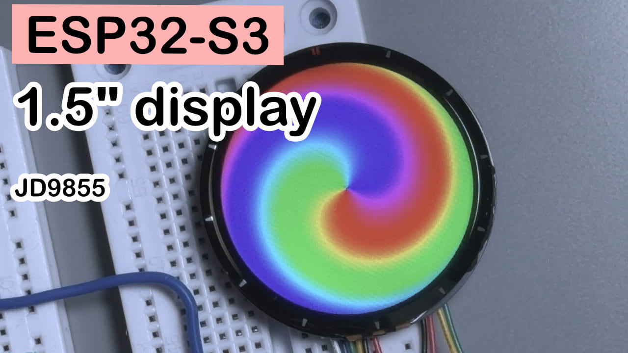
Difficulty: ⭐⭐⭐☆☆ (faster if you’ve done some microcontroller work before; pure beginners can still get it running by copying along) Estimated time: 30–45 minutes (not counting the wait for your Taobao order to arrive) Test environment: Arduino IDE 2.3.8 + ESP32 Arduino Core 3.3.10 (based on ESP-IDF v5 — you must be on this major version; more on why later)
One-line summary: Drive a 1.5-inch TK015F5785 round display over QSPI with an ESP32-S3 — the vendor lists the driver as ST77916, but reading the IC ID reveals it’s actually JD9855. This tutorial uses ESP-IDF’s built-in
esp_lcd_panel_ioto hand-write a mini driver in a single file of a few dozen lines, then runs three lookup-table animations — Plasma flow, rainbow wheel, and radial ripple — with no libraries installed and no calls tosin/atan2/sqrtat runtime. Silky-smooth full-screen motion in 30 minutes.
Foreword
I also started out thinking lighting up a round display would be one of those five-minute jobs — “plug it in, throw a color block at it, done.” The vendor said the driver IC was ST77916, which is already in the GFX library for Arduino. But after uploading the code, the screen just faded from black to full white… so I was properly stuck. Later I asked the vendor for the ESP-IDF driver code and found out the actual driver on this panel is JD9855 — and reading the panel’s IC ID (the code returned is FF 98 55 00) confirmed the driver chip really is JD9855. To make it easy for anyone to replicate, I just used ESP-IDF’s built-in esp_lcd_panel_io to hand-roll a mini driver of a few dozen lines — no library to install, no font to configure, not even a dedicated header file. It all goes into a single .ino and just runs.
This tutorial walks through the whole process of taking the 1.5-inch TK015F5785 round display from “a piece of black glass on arrival” to “full-screen flowing color animation” — covering wiring, how the driver works, and three smooth animation algorithms that never call sin/atan2/sqrt. Follow along and your round display will be spinning within 30 minutes.
TL;DR (in a hurry? read this):
- Wiring: SCLK→GPIO6, D0→GPIO15, D1→GPIO7, D2→GPIO11, D3→GPIO12, CS→GPIO16
- In the Arduino IDE choose Board = ESP32S3 Dev Module, USB CDC On Boot = Enabled
- No third-party libraries needed — the code relies entirely on ESP-IDF’s built-in
esp_lcd_panel_io; the core version must be v3.x- Copy-paste the whole .ino, compile, flash, and on power-up you’ll get a full-screen flowing color animation. If nothing shows, you’ve hit a pitfall — scroll down to “Troubleshooting”
Result
On power-up the screen automatically cycles through three colorful animations generated by lookup-table algorithms, dwelling on each for 6 seconds. The whole loop is stutter-free with no line-scan tearing:
- Plasma Flow: colors flow continuously like a liquid
- Rainbow Wheel: the full spectrum rotates slowly around the center, like a palette that never stops spinning
- Radial Ripple: ripples of color spread outward from the center
The moment you power up you get a full-screen animation — no extra input needed. It’s a great “yes, this display is really alive” sanity-check experiment.
Components
The dev board (ESP32-S3) isn’t covered in detail here; this section only describes the core parts besides the board.
TK015F5785 Round Display
The TK015F5785 is a 1.5-inch circular IPS display (driver IC JD9855). Its job is to render the pixel data the ESP32-S3 sends into an actual image, and in this project it’s the final visual surface that carries the three lookup-table animations. Unless otherwise noted, every spec in the table below comes from the module datasheet supplied by the vendor:
| Spec | Value / Description | Source |
|---|---|---|
| Size | 1.5 inch | Vendor datasheet |
| LCD type | IPS, full viewing angle | Vendor datasheet |
| Resolution | 360 × 360 | Vendor datasheet |
| Driver IC | JD9855 (the same model is also sold in an ST77916 variant — go by the measured IC ID) | Vendor datasheet + measured |
| Active area | Φ38.16 mm (diameter) | Vendor datasheet |
| Outline dimensions | 44.32 × 44.32 × 3.5 mm | Vendor datasheet |
| Pixel pitch | 0.106 × 0.106 mm | Vendor datasheet |
| Colors | 65K (RGB565, 16-bit/pixel) | Vendor datasheet |
| Brightness | 500 cd/m² | Vendor datasheet |
| Backlight | 4 white LEDs in parallel | Vendor datasheet |
| Operating temperature | -20 ~ 60 ℃ | Vendor datasheet |
| Interface | QSPI (SCLK + D0~D3 + CS) | Measured in this tutorial |
| Clock | 20 MHz (test value for this tutorial) | Measured |
Confirm the version before ordering: The vendor’s module datasheet labels this panel as “interface RGB / driver IC ST77916 or JD9855” — meaning the same TK015F5785 model ships in different driver-IC and interface combinations. This tutorial targets the JD9855 + QSPI version (in the foreword I only confirmed the chip wasn’t the initially claimed ST77916 by reading the IC ID =
FF 98 55 00). If you ended up with the ST77916 version or an RGB-interface version, both the init register sequence and the wiring have to change — you can’t just copy this code.
The round display’s physical active area is a circle of diameter Φ38.16 mm, which at 0.106 mm/pixel works out to exactly a pixel radius of 180 — so the code’s R2MAX = 180² actively forces pixels outside the circle to black, keeping the round edge clean (see Troubleshooting item 4).
The reason to pick it is straightforward: a QSPI interface adds 3 more data lines over traditional SPI, pushing data at 4× the bandwidth. At a pixel count like 360×360, single-line SPI would give you an ugly framerate.
Pinout
| Pin | Function |
|---|---|
| SCLK | QSPI clock line |
| D0 / D1 / D2 / D3 | The four QSPI data lines (transferred in parallel in Quad Mode) |
| CS | Chip select; pull low to select this screen |
| BL (backlight) | Backlight control; not broken out on some modules |
| VCC | Power, usually 3.3V |
| GND | Common ground |
JD9855 (Driver IC)
The JD9855 is a single-chip TFT LCD driver IC from chip vendor Jadard, integrated into the display module. It has a built-in frame buffer (GRAM); its job is to write the incoming pixel data into that buffer and drive the liquid-crystal cells to display color. In this project its role is to execute the init register sequence and the RAMWR pixel-write commands sent over esp_lcd_panel_io.
The good news is the JD9855 has a public datasheet (the Preliminary V0.00 version published by chip vendor Jadard in October 2023). Per the datasheet, the key specs are:
| Spec | Value / Description | Source |
|---|---|---|
| Drive capability | Single-chip SOC driving a-Si TFT, up to 360 RGB×390 (Dual-Gate=780) dots, 540-channel source drive | Features / Intro |
| Built-in frame buffer | 360×390×18 bit (~315 KB GRAM) | Features |
| Supported interfaces | 8080 parallel (8-bit), RGB (6-bit), SPI (8/9-bit, 2-lane), QSPI (DDR supported), MIPI-DSI | System Interface |
| Color format | RGB565 (16-bit) / RGB666 (18-bit) | Color Format |
| I/O voltage | 1.65V ~ 3.3V | Features |
| Operating temperature | -40 ~ +85 ℃ | Features |
This datasheet lays out the bit definitions and timing for commands like 0x2A (CASET), 0x2B (RASET), 0x2C (RAMWR), 0x36 (MADCTL), and 0x3A (COLMOD) very clearly — exactly the standard commands used in this tutorial’s code. One thing to note: what the datasheet publishes is the command set and timing. Panel-tuning parameters like Gamma correction, power-boost sequencing, and vendor-specific sub-commands (such as the 0xDE / 0xDF / 0xC3 “command-bank switch” registers in our init sequence) still belong to the panel vendor’s privately tuned init table, calibrated per screen. For these you just copy the vendor’s sequence verbatim and the panel lights up — there’s no need to dig into what every single entry means.
BOM
| Part | Qty | Notes |
|---|---|---|
| ESP32-S3 dev board | 1 | A version with PSRAM is recommended, so the angle lookup table can fall back gracefully |
| TK015F5785 round display module (JD9855 / QSPI) | 1 | Make sure it’s the JD9855 + QSPI version (the same model is also sold as ST77916/RGB — see Components) |
| Dupont jumper wires (female-to-female, depending on the module’s pin header) | 6+ | SCLK / D0~D3 / CS is 6 wires, plus VCC / GND |
Wiring
| Display pin | To ESP32-S3 pin |
|---|---|
| SCLK | GPIO6 |
| D0 | GPIO15 |
| D1 | GPIO7 |
| D2 | GPIO11 |
| D3 | GPIO12 |
| CS | GPIO16 |
| BL (backlight) | Not broken out on this module — can’t be software-controlled; just stays on once powered |
| VCC | 3.3V |
| GND | GND |
Double-check each wire after wiring up — it’ll save you 80% of your debugging time. QSPI has four data lines, and crossing two of them usually doesn’t produce a black screen but a garbled one, which is much harder to chase down than solid black.
Required Libraries
Good news: you don’t need to install any third-party libraries. The whole driver calls ESP-IDF’s built-in driver/spi_master.h, esp_lcd_panel_io.h, and esp_heap_caps.h directly — these headers ship with the Arduino ESP32 core.
The one hard requirement: the ESP32 board core in the Arduino IDE must be v3.x (based on ESP-IDF v5). The v2.x core sits on ESP-IDF v4.4, where the esp_lcd_panel_io_tx_param / esp_lcd_panel_io_tx_color API has different behavior and different header paths — compiling straight off will throw “symbol not found” or “function signature mismatch” errors.
How to upgrade: Arduino IDE → Tools → Board → Boards Manager, search for “esp32”, and update the espressif core package to 3.x or newer.
Full Code
The code is a single file — copy-paste it into a new .ino and you can compile. Note the CS pin is
16(an older draft version once had a typo of160, which doesn’t exist — see Troubleshooting item 1).
/*
 * =============================================================================
 *  TK015F5785 Round Display (JD9855, QSPI) Single-File Color Demo — Arduino IDE version
 * =============================================================================
 *
 *  ✦ Single file: driver + demo all in this one .ino. Copy-paste, no external files needed.
 *
 *  Demo (3 scenes auto-cycling, ~6 seconds each, all silky-smooth):
 *    [1] Plasma Flow      — colors flowing like a liquid (sin lookup table)
 *    [2] Rainbow Wheel    — full spectrum + slow rotation (precomputed angle lookup)
 *    [3] Radial Ripple    — colorful ripples from center outward (r² phase)
 *
 *  Full-screen flowing color the moment you power up — an immediate visual
 *  proof that "the screen is lit + colors are correct", great as a bring-up demo.
 *
 *  Performance key: every scene's per-pixel math is "table lookup + integer add/sub",
 *                   with no calls to sin/atan2/sqrt, so each frame renders fast — no
 *                   visible line-scan, all silky-smooth.
 *
 *  Hardware: ESP32-S3 + TK015F5785 (JD9855, QSPI)
 *    SCLK=6  D0=15  D1=7  D2=11  D3=12  CS=16  Backlight=-1 (not broken out, not controllable)
 *  Dependency: only the Arduino IDE esp32 board core v3.x. No external library / no fonts / no extra headers.
 *  Upload: Board=ESP32S3 Dev Module, USB CDC On Boot=Enabled, serial 115200.
 * =============================================================================
 */

#include <Arduino.h>
#include <math.h>
#include <initializer_list>
#include "driver/spi_master.h"
#include "esp_lcd_panel_io.h"
#include "esp_heap_caps.h"

#ifndef M_PI
#define M_PI 3.14159265358979323846
#endif

/* ----------------------------- Pin config ----------------------------- */
/* Keep in sync with the HelloWorld / test program; update both if you rewire */
#define PIN_LCD_SCLK   6
#define PIN_LCD_D0     15
#define PIN_LCD_D1     7
#define PIN_LCD_D2     11
#define PIN_LCD_D3     12
#define PIN_LCD_CS     16
#define PIN_LCD_BL     -1      /* Backlight; -1 means not controlled */ // This module doesn't break it out, so it can't be controlled

/* =====================================================================
 *  Display driver (JD9855 QSPI) — copy as-is, usually no need to modify
 *  Principle: Arduino-ESP32 3.x is built on ESP-IDF, so we drive QSPI
 *  directly via esp_lcd_panel_io.
 * ===================================================================== */
#define JD9855_SWRESET 0x01
#define JD9855_CASET   0x2A
#define JD9855_RASET   0x2B
#define JD9855_RAMWR   0x2C
#define JD9855_MADCTL  0x36
#define JD9855_COLMOD  0x3A
#define JD9855_SLPOUT  0x11
#define JD9855_DISPON  0x29

class JD9855_QSPI {
public:
    static constexpr int H_RES = 360;
    static constexpr int V_RES = 360;

    /* Standard RGB565 */
    static uint16_t color565(uint8_t r, uint8_t g, uint8_t b)
    {
        return ((uint16_t)(r & 0xF8) << 8) | ((uint16_t)(g & 0xFC) << 3) | (b >> 3);
    }

    bool begin(int sclk, int d0, int d1, int d2, int d3, int cs, int backlight = -1)
    {
        if (backlight >= 0) { pinMode(backlight, OUTPUT); digitalWrite(backlight, HIGH); }

        spi_bus_config_t buscfg = {};
        buscfg.sclk_io_num  = sclk;
        buscfg.data0_io_num = d0;
        buscfg.data1_io_num = d1;
        buscfg.data2_io_num = d2;
        buscfg.data3_io_num = d3;
        buscfg.max_transfer_sz = H_RES * V_RES * 2;
        esp_err_t ret = spi_bus_initialize(SPI2_HOST, &buscfg, SPI_DMA_CH_AUTO);
        if (ret != ESP_OK) { log_e("spi_bus_initialize: %s", esp_err_to_name(ret)); return false; }

        esp_lcd_panel_io_spi_config_t io_config = {};
        io_config.cs_gpio_num        = cs;
        io_config.dc_gpio_num        = -1;
        io_config.spi_mode           = 3;
        io_config.pclk_hz            = 20 * 1000 * 1000;
        io_config.trans_queue_depth  = 10;
        io_config.lcd_cmd_bits       = 32;
        io_config.lcd_param_bits     = 8;
        io_config.flags.quad_mode    = true;
        ret = esp_lcd_new_panel_io_spi(SPI2_HOST, &io_config, &io);
        if (ret != ESP_OK) { log_e("esp_lcd_new_panel_io_spi: %s", esp_err_to_name(ret)); return false; }

        sendCmd(JD9855_SWRESET);
        delay(20);
        sendInitCommands();
        return true;
    }

    /* Push an RGB565 (little-endian) buffer to a rectangular region */
    void pushRect(int x, int y, int w, int h, const uint16_t *data)
    {
        if (w <= 0 || h <= 0) return;
        setAddrWindow(x, y, x + w - 1, y + h - 1);
        size_t n = (size_t)w * h;
        ensureDmaBuf(n * 2);
        for (size_t i = 0; i < n; i++) {
            uint16_t c = data[i];
            dma_buf[i * 2]     = c >> 8;
            dma_buf[i * 2 + 1] = c & 0xFF;
        }
        sendColor(JD9855_RAMWR, dma_buf, n * 2);
    }

    /* Fill the whole screen (line by line, very low memory use) */
    void fillScreen(uint16_t color)
    {
        uint8_t hi = color >> 8, lo = color & 0xFF;
        const int BUF_PIX = H_RES;
        ensureDmaBuf(BUF_PIX * 2);
        for (int i = 0; i < BUF_PIX; i++) { dma_buf[i*2] = hi; dma_buf[i*2+1] = lo; }
        for (int y = 0; y < V_RES; y++) {
            setAddrWindow(0, y, H_RES - 1, y);
            sendColor(JD9855_RAMWR, dma_buf, BUF_PIX * 2);
        }
    }

private:
    esp_lcd_panel_io_handle_t io = nullptr;
    uint8_t *dma_buf = nullptr;
    size_t   dma_buf_size = 0;

    void ensureDmaBuf(size_t need)
    {
        if (dma_buf_size >= need) return;
        if (dma_buf) free(dma_buf);
        dma_buf = (uint8_t *)heap_caps_malloc(need, MALLOC_CAP_DMA);
        if (!dma_buf) dma_buf = (uint8_t *)heap_caps_malloc(need, MALLOC_CAP_8BIT);
        dma_buf_size = need;
    }

    void setAddrWindow(int x0, int y0, int x1, int y1)
    {
        uint8_t caset[4] = { (uint8_t)(x0>>8),(uint8_t)(x0&0xFF),(uint8_t)(x1>>8),(uint8_t)(x1&0xFF) };
        uint8_t raset[4] = { (uint8_t)(y0>>8),(uint8_t)(y0&0xFF),(uint8_t)(y1>>8),(uint8_t)(y1&0xFF) };
        sendCmd(JD9855_CASET, caset, 4);
        sendCmd(JD9855_RASET, raset, 4);
    }

    void sendCmd(uint8_t cmd, const uint8_t *data = nullptr, size_t len = 0)
    {
        uint32_t c = ((uint32_t)cmd << 8) | (0x02UL << 24);
        esp_lcd_panel_io_tx_param(io, c, data, len);
    }
    void sendCmd(uint8_t cmd, std::initializer_list<uint8_t> data)
    {
        sendCmd(cmd, data.begin(), data.size());
    }

    void sendColor(uint8_t cmd, const uint8_t *data, size_t len)
    {
        uint32_t c = ((uint32_t)cmd << 8) | (0x32UL << 24);
        esp_lcd_panel_io_tx_color(io, c, data, len);
    }

    /* JD9855 vendor init sequence (ported from the ESP-IDF esp_lcd_jd9855 driver) */
    void sendInitCommands()
    {
        sendCmd(0xFF, {0x20, 0x10, 0x00});
        sendCmd(JD9855_MADCTL, {0x00});
        sendCmd(JD9855_COLMOD, {0x55});
        sendCmd(0xDE, {0x00});
        sendCmd(0xDF, {0x98, 0x55});
        sendCmd(0xCE, {0x0D, 0x00});
        sendCmd(0xD8, {0x08, 0x00});
        sendCmd(0xB2, {0x30});
        sendCmd(0xB7, {0x01, 0x35, 0x01, 0x5D});
        sendCmd(0xBB, {0x1B, 0x64, 0xE3, 0x34, 0x3E, 0xF3});
        sendCmd(0xBC, {0x00, 0x1A, 0xF3, 0xC0});
        sendCmd(0xC0, {0x22, 0xC1});
        sendCmd(0xC3, {0x00, 0x01, 0x8D, 0x0B, 0x08, 0x48, 0x07, 0x04, 0x62, 0x30, 0x30});
        sendCmd(0xC4, {0x40, 0x00, 0xAD, 0x68, 0x37, 0x07, 0x04, 0x16, 0x43, 0x07, 0x04});
        sendCmd(0xC8, {0x3F, 0x2D, 0x22, 0x1D, 0x1D, 0x1F, 0x1B, 0x1C, 0x1B, 0x1B, 0x17, 0x0D, 0x09, 0x05, 0x01, 0x02});
        sendCmd(0xC8, {0x3F, 0x2D, 0x22, 0x1D, 0x1D, 0x1F, 0x1B, 0x1C, 0x1B, 0x1B, 0x17, 0x0D, 0x09, 0x05, 0x01, 0x02});
        sendCmd(0xD3, {0x28, 0x13});
        sendCmd(0xD9, {0x00, 0x00, 0xFF, 0x00, 0xF0, 0x00});
        sendCmd(0xDE, {0x01});
        sendCmd(0xB7, {0x17, 0xA7, 0x64, 0x3B, 0x06, 0x36, 0x18, 0x18});
        sendCmd(0xBE, {0x00});
        sendCmd(0xC1, {0x04, 0x40, 0x90, 0x08});
        sendCmd(0xC2, {0x00, 0x16, 0xDA, 0xE7});
        sendCmd(0xC4, {0x72, 0x12});
        sendCmd(0xC7, {0x00, 0x00, 0x02, 0x32, 0x10, 0x32});
        sendCmd(0xC8, {0x00, 0x00, 0x0B, 0x32, 0x12, 0x2E});
        sendCmd(0xC9, {0x00, 0x0A, 0x08, 0x06, 0x04});
        sendCmd(0xCA, {0x1E, 0x1F, 0x10, 0x17, 0x18});
        sendCmd(0xCB, {0x01, 0x0B, 0x09, 0x07, 0x05});
        sendCmd(0xCC, {0x1E, 0x1F, 0x11, 0x17, 0x18});
        sendCmd(0xCD, {0x31, 0x25, 0x27, 0x29, 0x2B});
        sendCmd(0xCE, {0x3F, 0x3E, 0x21, 0x37, 0x38});
        sendCmd(0xCF, {0x30, 0x24, 0x26, 0x28, 0x2A});
        sendCmd(0xD0, {0x3F, 0x3E, 0x20, 0x37, 0x38});
        sendCmd(0xD1, {0x06, 0x30, 0xA5, 0xDB, 0x30});
        sendCmd(0xD3, {0x3B, 0x08, 0x00, 0x00, 0x00, 0x00});
        sendCmd(0xD4, {0x67, 0x00, 0x00, 0x01, 0x00, 0x01});
        sendCmd(0xD5, {0x10, 0x10, 0x07, 0x07, 0x0F, 0x94, 0x26});
        sendCmd(0xD6, {0x00, 0x00, 0x40});
        sendCmd(0xD7, {0x01, 0x84, 0x20});
        sendCmd(0xDE, {0x02});
        sendCmd(0xB6, {0x1C});
        sendCmd(0xDE, {0x00});
        sendCmd(0x2A, {0x00, 0x00, 0x01, 0x67});
        sendCmd(0x2B, {0x00, 0x00, 0x01, 0x67});
        sendCmd(0x35);
        sendCmd(0x36, {0x00});
        sendCmd(0x3A, {0x55});
        sendCmd(0xDE, {0x00});
        sendCmd(0x11);            /* Exit sleep */
        delay(120);
        sendCmd(0x29);            /* Display on */
        delay(10);
    }
};

/* =====================================================================
 *  Demo section — the part worth reading
 *  Idea: each frame computes every pixel's color row by row and pushes it to the screen.
 *       Anything "position-dependent but time-independent" (sin, hue, angle) is
 *       pre-baked into a lookup table, so at runtime each pixel only does
 *       "table lookup + integer add/sub" — that's why all three scenes are silky-smooth.
 * ===================================================================== */
JD9855_QSPI lcd;

static constexpr int W = JD9855_QSPI::H_RES;     /* 360 */
static constexpr int H = JD9855_QSPI::V_RES;     /* 360 */
static constexpr int CX = W / 2;                  /* center x */
static constexpr int CY = H / 2;                  /* center y */
static constexpr int RADIUS = 180;                /* visible radius of the round screen */
static constexpr int R2MAX  = RADIUS * RADIUS;    /* r² threshold outside the circle (180²=32400) */

static const int BLOCK_H = 40;             /* Render + push 40 rows per batch — far fewer pushes */
uint16_t blockBuf[W * BLOCK_H];            /* Block buffer (360*40*2=28KB, internal RAM, no PSRAM needed) */
uint8_t  sinTab[256];       /* Sine lookup table: sinTab[i] = sin(i/256*2π)*127+128 */
uint16_t hsvTab[256];       /* Hue (0-255) -> RGB565 lookup (max saturation/value) */
uint8_t *angleTab = nullptr;/* Per-pixel angle-from-center lookup (360*360B), so disc scenes never call atan2 */

/* HSV(0-359, 0-255, 0-255) -> RGB565 */
uint16_t hsvTo565(int h, uint8_t s, uint8_t v)
{
    uint8_t region = h / 60;
    uint8_t rem    = (h - region * 60) * 255 / 60;
    uint8_t p = (uint16_t)v * (255 - s) / 255;
    uint8_t q = (uint16_t)v * (255 - (uint16_t)s * rem / 255) / 255;
    uint8_t t = (uint16_t)v * (255 - (uint16_t)s * (255 - rem) / 255) / 255;
    uint8_t r, g, b;
    switch (region) {
        case 0:  r = v; g = t; b = p; break;
        case 1:  r = q; g = v; b = p; break;
        case 2:  r = p; g = v; b = t; break;
        case 3:  r = p; g = q; b = v; break;
        case 4:  r = t; g = p; b = v; break;
        default: r = v; g = p; b = q; break;
    }
    return JD9855_QSPI::color565(r, g, b);
}

/* Build the sin and hue tables once at startup; rendering then only does lookups */
void buildTables()
{
    for (int i = 0; i < 256; i++) {
        float s = sinf(i / 256.0f * 2.0f * (float)M_PI);
        sinTab[i] = (uint8_t)(s * 127.0f + 128.0f);
    }
    for (int h = 0; h < 256; h++) {
        hsvTab[h] = hsvTo565(h * 360 / 256, 255, 255);
    }
}

/* Precompute every pixel's angle relative to the center (atan2), stored as a 0-255 lookup table.
   At runtime the disc scenes just read the table — they never call atan2f per frame (that was
   the original culprit for the stutter). Computed once in setup, so the cost doesn't matter.
   We prefer internal RAM (~126KB); if that's full we fall back to PSRAM; if neither is
   available we leave it nullptr and the scene degrades to atan2f (still watchable, just choppy). */
void buildAngleTable()
{
    size_t n = (size_t)W * H;
    angleTab = (uint8_t *)heap_caps_malloc(n, MALLOC_CAP_INTERNAL | MALLOC_CAP_8BIT);
    if (!angleTab) angleTab = (uint8_t *)heap_caps_malloc(n, MALLOC_CAP_SPIRAM);
    if (!angleTab) { Serial.println(F("[WARN] angleTab alloc failed, disc scene will be slower")); return; }
    for (int y = 0; y < H; y++) {
        for (int x = 0; x < W; x++) {
            float dx = (float)(x - CX), dy = (float)(y - CY);
            float a = atan2f(dy, dx) / (2.0f * (float)M_PI);   /* -0.5..0.5 */
            angleTab[y * W + x] = (uint8_t)(a * 256.0f);        /* wrap-around mapped to 0-255 */
        }
    }
    Serial.printf("[INIT] angle table %d KB ready (disc scene will be silky-smooth)\n", (int)(n / 1024));
}

inline uint8_t sin8(int phase) { return sinTab[(uint8_t)phase]; }

/* ---- Scene 1: Plasma Flow (pure table lookup) ---- */
inline uint16_t plasmaPixel(int x, int y, int t)
{
    int v = sin8(x * 3 + t)
          + sin8(y * 3 - t * 2)
          + sin8((x + y) * 2 + t / 2)
          + sin8((x - y) * 2 - t / 2);
    return hsvTab[(uint8_t)(v / 4 + t)];
}

/* ---- Scene 2: Rainbow Wheel (angle lookup + r², all-integer) ---- */
inline uint16_t wheelPixel(int x, int y, int t)
{
    int dx = x - CX, dy = y - CY;
    int r2 = dx * dx + dy * dy;
    if (r2 > R2MAX) return 0;                 /* outside the circle → black, keeps the edge clean */
    int ang = angleTab ? angleTab[y * W + x]
                       : (int)(atan2f((float)dy, (float)dx) / (2.0f * (float)M_PI) * 256.0f);
    int hue = ang + r2 / 200 + t;             /* layer hue along the radius for a spiral palette */
    return hsvTab[(uint8_t)hue];
}

/* ---- Scene 3: Radial Ripple (r² used directly as phase, no sqrt needed) ---- */
inline uint16_t ripplePixel(int x, int y, int t)
{
    int dx = x - CX, dy = y - CY;
    int r2 = dx * dx + dy * dy;
    if (r2 > R2MAX) return 0;
    int v = sin8(r2 / 80 - t * 3);            /* ripple phase: spreads with distance + time */
    return hsvTab[(uint8_t)(v + r2 / 400)];
}

/* Render one frame: compute BLOCK_H rows then push the whole block at once (9 pushes
   instead of 360 — saves command overhead and bumps the framerate, and refreshing 40 rows
   at a time also greatly softens the line-scan feel). sceneId picks the pixel function (0=plasma, 1=wheel, 2=ripple) */
void renderFrame(int sceneId, int t)
{
    for (int by = 0; by < H; by += BLOCK_H) {
        int bh = (H - by < BLOCK_H) ? (H - by) : BLOCK_H;
        for (int y = 0; y < bh; y++) {
            int yy = by + y;
            for (int x = 0; x < W; x++) {
                uint16_t c;
                switch (sceneId) {
                    case 0:  c = plasmaPixel(x, yy, t); break;
                    case 1:  c = wheelPixel(x, yy, t);  break;
                    default: c = ripplePixel(x, yy, t); break;
                }
                blockBuf[y * W + x] = c;
            }
        }
        lcd.pushRect(0, by, W, bh, blockBuf);
    }
}

/* Scene names */
const char *SCENE_NAMES[] = { "Plasma Flow", "Rainbow Wheel", "Radial Ripple" };
const int      N_SCENES   = 3;
const uint32_t SCENE_MS   = 6000;    /* dwell on each scene for 6 seconds */

int      curScene   = 0;
uint32_t sceneStart = 0;

/* ----------------------------- setup ------------------------------- */
void setup()
{
    Serial.begin(115200);
    delay(200);
    Serial.println();
    Serial.println(F("[TK015F5785] Single-file color demo (JD9855 QSPI)"));

    Serial.println(F("[LCD] begin..."));
    bool ok = lcd.begin(PIN_LCD_SCLK, PIN_LCD_D0, PIN_LCD_D1, PIN_LCD_D2,
                        PIN_LCD_D3, PIN_LCD_CS, PIN_LCD_BL);
    if (!ok) {
        Serial.println(F("[LCD] init FAILED! check wiring / board core version (needs esp32 v3.x)"));
        while (true) { delay(1000); }
    }
    Serial.println(F("[LCD] init OK"));

    buildTables();
    buildAngleTable();          /* precompute the angle table so disc scenes are silky-smooth */
    lcd.fillScreen(0);
    sceneStart = millis();
    Serial.printf("[DEMO] scene 1/%d: %s\n", N_SCENES, SCENE_NAMES[curScene]);
}

/* ----------------------------- loop -------------------------------- */
void loop()
{
    int t = (int)(millis() / 12);     /* animation step — bigger means faster */

    renderFrame(curScene, t);

    if (millis() - sceneStart >= SCENE_MS) {
        sceneStart = millis();
        curScene   = (curScene + 1) % N_SCENES;
        Serial.printf("[DEMO] scene %d/%d: %s\n",
                      curScene + 1, N_SCENES, SCENE_NAMES[curScene]);
    }
}
Code Walkthrough
First, in JD9855_QSPI::begin(), spi_bus_initialize brings up a QSPI bus that runs over all four data lines, and then esp_lcd_new_panel_io_spi attaches an LCD IO device with quad_mode = true. This is the linchpin of the whole driver — without quad_mode, only one of the four data lines actually carries data and the framerate falls off a cliff.
Second, sendInitCommands() is a verbatim copy of the panel vendor’s register init table, sent entry by entry over esp_lcd_panel_io_tx_param. You don’t need to understand what each register means; if you change screens, you don’t touch this block.
Third — and this is the real point of the code: none of the three animation scenes call slow functions like sin, atan2, or sqrt at runtime. Instead, they’re all pre-baked into lookup tables (sinTab, hsvTab, angleTab) during setup(), so at runtime every pixel only does “table lookup + integer add/sub”. That’s also why 360×360 = 129,600 pixels per frame still stays smooth and tear-free.
Fourth, renderFrame() doesn’t push row by row — it accumulates a full BLOCK_H = 40 rows and then hands the whole block to pushRect in one shot. 360 rows only need 9 pushes, saving a huge amount of SPI command overhead versus pushing 360 times line by line.
Troubleshooting
Don’t panic — the issues below cover most of the “my round display won’t light up” reports:
1. Solid black after power-up, and the serial monitor never prints [LCD] init OK First check whether the CS pin is wired correctly — this was the easiest pitfall to hit in early drafts of this code: PIN_LCD_CS was once mistyped as 160 (a GPIO number that doesn’t exist). The code block in this article is already fixed to 16. If you copied an older version from elsewhere, make absolutely sure that line says 16, not 160.
2. The screen lights up but is garbled, colors are wrong Most likely D0~D3 are out of order. QSPI is sensitive to line order — this isn’t the same as swapping MOSI/MISO on plain SPI. Cross-check each wire against the wiring table; don’t just go by feel.
3. Compile error: esp_lcd_panel_io.h not found That means your Arduino ESP32 core is still v2.x (based on ESP-IDF v4.4). Open Boards Manager and upgrade the espressif esp32 core to v3.x or newer, then recompile.
4. The four corners of the round display stay black — is it wired wrong? That’s normal, not a fault. The code sets R2MAX = 180², and any pixel beyond that radius is intentionally forced to black, because the round display’s physical active area is a circle anyway and the four corners are covered by the bezel. Handling it this way actually gives a cleaner edge.
5. Serial prints angleTab alloc failed and the disc scene turns choppy Internal RAM wasn’t enough to allocate this ~126 KB (360×360 bytes) angle table. The code already has a fallback chain: try internal RAM first, then PSRAM, and if neither works, compute on the fly with atan2f (still watchable, but noticeably slower). If your board has no PSRAM and the disc scene always feels choppier than the other two, that’s why — switching to a board with PSRAM cures it for good.
6. The backlight is always on and won’t turn off The code sets PIN_LCD_BL to -1, and the comment says “this module doesn’t break it out, so it can’t be controlled”. If your module does break out a backlight pin, change this macro to the corresponding GPIO number and pass it into begin() — you’ll then get software dimming / on-off control.
FAQ
Q: How do I light up a round display with an ESP32? A: The core of it is using the QSPI interface + esp_lcd_panel_io to talk to the driver IC directly, without depending on a general-purpose graphics library like TFT_eSPI. Wire up SCLK/D0~D3/CS correctly and copy the panel vendor’s init register sequence verbatim — the panel lights up.
Q: What library should I use for a JD9855-driven round display? A: You don’t need an extra library. JD9855 isn’t built into mainstream graphics libraries (TFT_eSPI, the LVGL official driver list, etc.), so the safest bet is to do what this article does — call ESP-IDF’s built-in esp_lcd_panel_io API and hand-write a few dozen lines of init code.
Q: What’s the wiring difference between a QSPI display and a regular SPI one? A: Regular SPI has one data line (MOSI); QSPI has four (D0~D3) transferring in parallel, giving 4× the bandwidth. The trade-off is 3 extra wires, and you must set flags.quad_mode to true inside esp_lcd_panel_io_spi_config_t.
Q: Why does my ESP32-S3 round display stay black? A: The three most common causes, ranked by likelihood: the CS pin is wired wrong or the number is mistyped; the board core is older than v3.x so init fails; or the power supply is unstable (more obvious with longer QSPI traces). Whether the serial monitor prints [LCD] init OK will quickly tell you whether it’s a driver-layer issue or a wiring issue.
Q: How do I drive a display with esp_lcd_panel_io from the Arduino IDE? A: Three steps: spi_bus_initialize to set up the SPI bus; esp_lcd_new_panel_io_spi to create the LCD IO handle (this is where you specify CS / clock frequency / SPI mode / quad_mode); then esp_lcd_panel_io_tx_param to send commands and esp_lcd_panel_io_tx_color to send pixel data.
Q: Can I use the TFT_eSPI library with an ESP32 round display? A: TFT_eSPI mainly targets the driver ICs in its built-in support list, and an obscure QSPI chip like JD9855 isn’t on it. Forcing it usually means hacking the driver layer yourself, which is more headache than just hand-writing against the native ESP-IDF API.
Q: Is there enough memory for a 360×360 round display? A: Yes, but watch how you allocate. A full-screen single buffer takes 360×360×2 bytes ≈ 253 KB. This article uses block rendering (40 rows per block, ~28 KB), plus an optional 126 KB angle lookup table — internal RAM can basically hold all of it. There’s no need to bolt on PSRAM just for this screen (unless you want the peace of mind of keeping the angle table in internal RAM too).
Going Further
Once you’ve got the basic demo running, there are plenty of directions to keep tinkering with this round display:
- Swap the three lookup-table scenes for real-time data visualizations (CPU load, weather, heart rate, etc. — the round shape is great for gauges and dashboards)
- Hook up a touch layer or rotary encoder and turn it into an interactive circular control panel
- Port the same
esp_lcd_panel_ioapproach to other QSPI driver-IC displays - Crank up
BLOCK_Handpclk_hzand stress-test the framerate to find your specific module’s refresh-rate ceiling
References
- The official ESP-IDF LCD peripheral docs explain that the esp_lcd component is a chip-agnostic common API from Espressif that supports SPI LCD, I80 LCD, RGB/SRGB LCD, and other display types: ESP-IDF LCD Peripheral (ESP32-S3)
- ESP32-S3 series official datasheet (PDF, from Espressif)
- espressif/arduino-esp32 official GitHub repository
- The public JD9855 datasheet (the Preliminary V0.00 version released by chip vendor Jadard on 2023-10-17; the PDF mirror below is hosted by OSPTek) lists 540-channel source drive, 360 RGB×390 resolution, built-in GRAM, multiple interfaces (8080/SPI/QSPI/MIPI-DSI), and the full timing for commands such as CASET/RASET/RAMWR: JD9855 Data Sheet (Preliminary V0.00, PDF)