ESP32 + MAX7219 Electronic Hourglass | SPI Wiring + 45° Rotation Physics Engine Source Code
With one ESP32 and two MAX7219 8x8 dot-matrix modules, follow along to recreate the viral electronic hourglass. Covers the 45° rotation physics engine, SPI daisy-chain wiring, and the complete Arduino C++ source code, plus a troubleshooting guide. Aimed at makers who already know how to flash basic firmware.
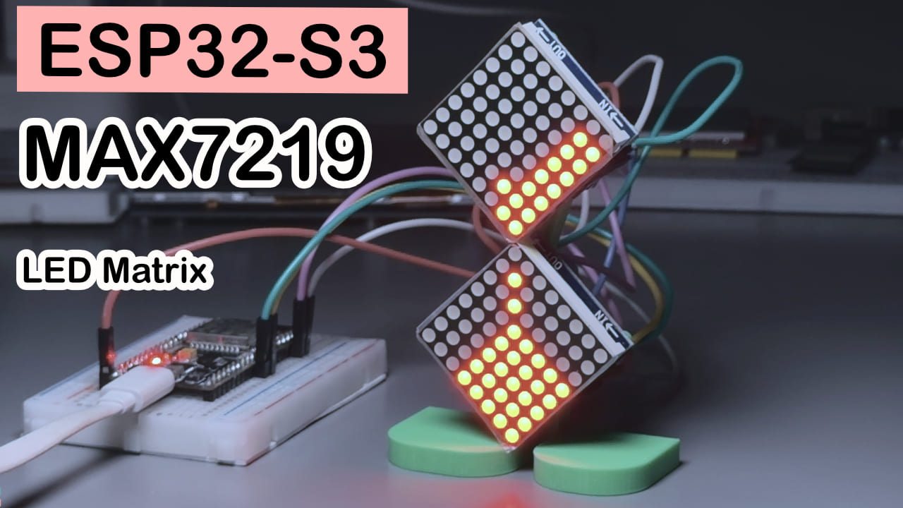
TL;DR (Quick start):
- Wiring: ESP32
GPIO23->DIN,GPIO18->CLK,GPIO5->CS; daisy-chain the two MAX7219 modules withDOUT->DIN- Power:
5V->VCC,GND->GND(do not reverse these - you have been warned)- Library: Search for
MD_MAX72xxin the Arduino Library Manager and install it;SPI.his built-in, no extra install needed- After flashing, the matrix will start “pouring sand” automatically - no buttons or sensors required to run
Difficulty: 3/5 stars (achievable if you have flashed code with the Arduino IDE before) Estimated time: 40 minutes (15 min wiring + 25 min flashing and debugging) Test environment: Arduino IDE 2.3.8 + ESP32 Arduino Core 3.3.10 + MD_MAX72xx v3.5.1
Preface
Have you ever scrolled past one of those electronic hourglasses where grains of sand drop down cell by cell and naturally pile up into a slope when tilted, and felt the urge to build one yourself? My first reaction was also “this must need a gyroscope and a pile of physics formulas,” but once I actually started, I realized the real challenge isn’t the hardware at all - it’s how to make two perfectly square dot-matrix modules “pretend” in code that they have been rotated 45 degrees and assembled into the shape of an hourglass. This article is a write-up of the gotchas I hit and the physics logic I figured out. Follow along, and you too can put a “sand-pouring” electronic desk ornament on your table using just one ESP32 and two MAX7219 modules.
Experiment Result
After power-on, the dot matrix automatically enters a loop: first it pours sand smoothly in the upright orientation, then it simulates tilting left and right so the sand piles up at a natural slope, and finally it does a full “flip,” turning the hourglass upside down so the pouring starts again. The whole process requires no button presses. My current experiment does not use a gyroscope - the tilt angles are hardcoded. The code has a built-in “pseudo-gyroscope” state machine that automatically switches between poses.
Component Notes
The development board (ESP32) should be familiar to everyone, so I won’t belabor it here - let’s focus on the MAX7219.
MAX7219 - The “Translator” for LED Matrices
The MAX7219 is an LED driver chip that controls an entire 8x8 = 64-LED matrix using very few pins. In this project its job is to “translate” the ESP32’s limited GPIOs into a full drawable canvas - otherwise you’d have to run 64 wires to light up each LED individually, which makes your hands hurt just thinking about it.
You can think of it as a “translator”: the ESP32 only needs to send simple SPI commands (which row, which pixels to light), and the MAX7219 takes care of scanning and routing current to the corresponding LEDs in turn, fast enough that the human eye cannot perceive any flicker.
| Parameter | Value |
|---|---|
| Drive method | SPI (3-wire: DIN/CLK/CS) |
| LEDs per chip | 64 (8x8) |
| Operating voltage | 4.0V - 5.5V |
| Cascading | DOUT connects to the next chip’s DIN; supports daisy-chaining multiple chips |
| Brightness adjustment | 16 levels (this article uses level 5) |
The reason to pick it is that it’s cheap, widely available, and has a mature library. Two of them paired together can also be “physically rotated 45 degrees” to form the diamond outline of an hourglass - hard to beat on value for money.
Pinout
The MAX7219 module’s common pin layout is as follows (some vendors print the silkscreen in a different order - refer to the markings on the back of your module):
| Pin | Function |
|---|---|
| VCC / GND | Power positive / negative |
| DIN | Data input (connects to the previous stage’s DOUT or to the MCU) |
| DOUT | Data output (connects to the next stage’s DIN, for cascading) |
| CS | Chip-select signal |
| CLK | Clock signal |
BOM
| Component | Qty | Notes |
|---|---|---|
| ESP32 development board | 1 | Any model, as long as it has usable GPIOs |
| MAX7219 8x8 dot-matrix module | 2 | Recommend buying the same batch and model for more consistent color and brightness |
| Dupont jumper wires | Several | Recommend female-to-female for tidier jumps between modules |
Wiring
The text table is easy to misread row-by-row - I suggest reviewing the diagram above first to get the overall idea, then verify each wire against the table below.
| ESP32 | Module 1 (MAX7219 #1) | Module 2 (MAX7219 #2) |
|---|---|---|
| 5V | VCC (IN) -> VCC (OUT) | <- VCC (IN) |
| GND | GND (IN) -> GND (OUT) | <- GND (IN) |
| GPIO23 | DIN -> DOUT | -> DIN |
| GPIO5 | CS (IN) -> CS (OUT) | -> CS (IN) |
| GPIO18 | CLK (IN) -> CLK (OUT) | -> CLK (IN) |
I recommend double-checking each wire once you are done - it saves 80% of troubleshooting time, especially making sure VCC/GND are not reversed and the IN/OUT direction on each module is correct. These two are the most common reasons for rework.
Required Libraries
Open the Arduino IDE -> Library Manager and search for and install the following:
MD_MAX72xx(by MajicDesigns, current latest stable release v3.5.1) - the core library for driving the MAX7219 dot matrixSPI.h- bundled with the Arduino IDE, no separate install required
Quick tip: the MD_MAX72xx library ships with an official Hourglass example. If the code in this article doesn’t render quite right, compare it against the library’s bundled example to check whether you picked the wrong HARDWARE_TYPE for your module.
Full Code + Walkthrough
/*
  ================================================================
   ESP32 dual 8x8 MAX7219 electronic hourglass (45° rotation tiled version)
  ================================================================

  Hardware layout notes:
  ------------------------------------------------------------
  Two ordinary 8x8 MAX7219 dot-matrix modules, daisy-chained DIN->DOUT in order:
     [ESP32] --DIN--> [Module 1 (upper funnel)] --DOUT--> [Module 2 (lower funnel)]

  MD_MAX72XX's native addressing scheme is "row 0~7, column 0~(8*numDevices-1)",
  so 2 devices naturally give an 8-row x 16-column address space:
     Module 1 occupies columns 0~7   (after the 45° rotation this is the "upper funnel",
                                       tip at row 7, column 7)
     Module 2 occupies columns 8~15  (after the 45° rotation this is the "lower funnel",
                                       tip at row 0, column 8)

  Each module is physically rotated 45° and the two are tiled top-to-bottom; only the
  pair of cells (row 7, column 7) and (row 0, column 8) are physically adjacent - this
  is the hourglass "neck" and the only passage that allows a grain of sand to cross
  between modules. Apart from that, there is no physical adjacency between column 7
  and column 8 (the two diamonds only meet at a single vertex), so the code must
  explicitly mask out all other cross-column "teleports".

  Physical intuition for the gravity direction:
  ------------------------------------------------------------
  Because the whole module is physically rotated 45°, the module's own row and
  column directions are no longer vertical; they point at the "real-world" lower-
  left-45° and lower-right-45° respectively. Therefore:
     - Both directional components +1 at once (row+1 and col+1) corresponds to
       "straight down" in the real world.
     - Only row +1 (column unchanged) corresponds to "lower-left" in the real world
       (natural angle-of-repose of the sand pile).
     - Only column +1 (row unchanged) corresponds to "lower-right" in the real world
       (natural angle-of-repose of the sand pile).
  This is the origin of the "gravity vector" and "lateral slide component" in this
  code. When the hourglass is flipped (gravityDir changes from +1 to -1), both
  components flip sign simultaneously, and the physical interpretation stays
  self-consistent.

  Anti-ghosting / anti-single-frame-overspeed:
  ------------------------------------------------------------
  Each frame scans the cells in the reverse direction "gravity downstream ->
  gravity upstream" (when gravityDir=+1, scan from row 7,col 15 toward row 0,col 0;
  after a flip, scan the other way), which guarantees:
     1) Each grain moves at most one cell per frame - no chained judgments can
        cause "teleports."
     2) Whether a target cell is occupied is always decided against "the final
        state already settled for this frame," so two grains fighting for the
        same target cell in the same frame can't cause ghosting or lost grains.

  Pins (kept unchanged per the wiring you verified as working):
     DATA_PIN 23 (MOSI)   CLK_PIN 18 (SCK)   CS_PIN 5 (CS)

  Gyroscope:
  ------------------------------------------------------------
  No real gyroscope is connected yet; this code has a built-in "pseudo-gyroscope"
  state machine (fakeGyroX / fakeGyroZ) that, on a time loop, produces:
     upright steady pour -> tilt to one side -> level -> full flip inverted -> (repeat in reverse)
  When you later connect a real sensor such as an MPU6050, just hook up readRealGyro()
  and replace fakeGyroX/fakeGyroZ with real angles - the rest of the physics engine
  needs no changes.
  ================================================================
*/

#include <MD_MAX72xx.h>
#include <SPI.h>

// ---------------- Hardware configuration ----------------
#define HARDWARE_TYPE MD_MAX72XX::FC16_HW
#define MAX_DEVICES   2          // Only 2 8x8 modules

#define DATA_PIN  23  // VSPI MOSI
#define CLK_PIN   18  // VSPI SCK
#define CS_PIN    5   // VSPI CS0

MD_MAX72XX mx = MD_MAX72XX(HARDWARE_TYPE, DATA_PIN, CLK_PIN, CS_PIN, MAX_DEVICES);

// ---------------- Display orientation correction ----------------
// If after lighting up the matrix you find it is "upside down" or "the two modules
// are swapped left/right," just change these two macros - no need to touch the
// physics algorithm below.
#define FLIP_ROW           true   // Whether the row direction needs flipping (7-row)
#define SWAP_MODULE_ORDER  false  // If module 2 is wired into the daisy-chain before module 1, set to true

// ---------------- Logical grid ----------------
#define ROWS 8
#define COLS 16
// Neck: module 1 exit (7,7) <-> module 2 entrance (0,8)
#define NECK_A_R 7
#define NECK_A_C 7
#define NECK_B_R 0
#define NECK_B_C 8

bool sand[ROWS][COLS];

// ---------------- Physics engine parameters ----------------
#define SAND_TOTAL        42     // Total grains of sand; tune to taste (recommended 30~50)
#define TICK_MS           130    // Physics step length (ms); smaller = faster flow.
                                  // Tuned up to ~130ms, you can clearly see grains fall
                                  // cell by cell with the naked eye, and grains dropping
                                  // through the neck are naturally spaced one cell apart
                                  // (you can see 2~3 points falling with gaps at once).
                                  // If it still feels too fast, keep increasing it
                                  // (recommended range 100~180).
const float LATERAL_FRICTION = 0.85f;  // Lateral-slide "friction": not every frame
                                       // triggers a slide, creating a natural sense of pause

int   gravityDir  = 1;     // +1 = upright (module1 -> module2)   -1 = inverted (module2 -> module1)
float targetBias  = 0.0f;  // Target tilt bias [-1,1]
float currentBias = 0.0f;  // Smoothed current tilt bias (approaches targetBias slowly to avoid sudden jumps)

unsigned long lastTickMs = 0;

// ================================================================
//                        Sand physics engine
// ================================================================

inline int moduleOf(int c) { return (c < 8) ? 1 : 2; }

// Whether this is a legal neck crossing (the only pair of cells allowed to cross modules, bidirectional)
inline bool isNeckPair(int r, int c, int nr, int nc) {
  if (r == NECK_A_R && c == NECK_A_C && nr == NECK_B_R && nc == NECK_B_C) return true;
  if (r == NECK_B_R && c == NECK_B_C && nr == NECK_A_R && nc == NECK_A_C) return true;
  return false;
}

inline bool canMove(int r, int c, int nr, int nc) {
  if (nr < 0 || nr > 7 || nc < 0 || nc > 15) return false;   // Out of bounds
  if (sand[nr][nc]) return false;                             // Target already occupied
  if (moduleOf(c) != moduleOf(nc)) {                          // Cross-module?
    if (!isNeckPair(r, c, nr, nc)) return false;              // Only the neck is allowed
  }
  return true;
}

inline bool tryMove(int r, int c, int nr, int nc) {
  if (!canMove(r, c, nr, nc)) return false;
  sand[r][c]   = false;
  sand[nr][nc] = true;
  return true;
}

// Compute the "straight down" target cell (main gravity direction).
// Key point: when standing at the neck tip, (row+g, col+g) goes directly out of
// bounds (e.g. 7+1=8 exceeds 0~7), so it must be explicitly redirected to the
// cell on the opposite side of the neck, otherwise the grain gets stuck at the
// tip and cannot pass through.
inline void primaryTarget(int r, int c, int g, int &nr, int &nc) {
  if (g == 1  && r == NECK_A_R && c == NECK_A_C) { nr = NECK_B_R; nc = NECK_B_C; return; }
  if (g == -1 && r == NECK_B_R && c == NECK_B_C) { nr = NECK_A_R; nc = NECK_A_C; return; }
  nr = r + g;
  nc = c + g;
}

float random01() { return random(0, 10001) / 10000.0f; }

// One-step decision for a single grain: prefer straight down; if blocked, slide
// lower-left / lower-right according to the tilt bias
void moveGrain(int r, int c) {
  int g = gravityDir;
  int pnr, pnc;
  primaryTarget(r, c, g, pnr, pnc);

  // The larger the tilt, the more it tends to "skip straight down and slide
  // directly," simulating the shift of the real gravity component
  bool primaryFirst = random01() < (1.0f - fabsf(currentBias) * 0.6f);

  if (primaryFirst) {
    if (tryMove(r, c, pnr, pnc)) return;
  }

  // Lateral slide: component A (row direction only) / component B (column direction
  // only); the bias decides the order of attempts
  if (random01() < LATERAL_FRICTION) {
    bool aFirst = random01() < (0.5f - currentBias * 0.5f);
    int arn = r + g, acn = c;      // Component A: lower-left (or lower-right, depending on rotation direction)
    int brn = r,     bcn = c + g;  // Component B: the other side

    if (aFirst) {
      if (tryMove(r, c, arn, acn)) return;
      if (tryMove(r, c, brn, bcn)) return;
    } else {
      if (tryMove(r, c, brn, bcn)) return;
      if (tryMove(r, c, arn, acn)) return;
    }
  }

  // Fallback: if straight down was skipped because of the bias, make one more
  // attempt here, guaranteeing that as long as straight down is actually empty,
  // the grain will eventually fall (it won't be locked out by the bias logic)
  if (!primaryFirst) {
    tryMove(r, c, pnr, pnc);
  }
}

// One full frame of computation: scan in reverse "gravity downstream -> upstream"
// to prevent ghosting / overspeed falling
void updateSand() {
  int rStart, rEnd, rStep, cStart, cEnd, cStep;
  if (gravityDir == 1) {
    // Downstream = large row and column -> scan from (7,15) toward (0,0)
    rStart = 7; rEnd = -1; rStep = -1;
    cStart = 15; cEnd = -1; cStep = -1;
  } else {
    // After a flip, downstream = small row and column -> scan from (0,0) toward (7,15)
    rStart = 0; rEnd = 8; rStep = 1;
    cStart = 0; cEnd = 16; cStep = 1;
  }

  for (int r = rStart; r != rEnd; r += rStep) {
    for (int c = cStart; c != cEnd; c += cStep) {
      if (sand[r][c]) moveGrain(r, c);
    }
  }

  // Smoothly approach the target bias so the tilt / level transitions feel
  // silkier, not abrupt
  currentBias += (targetBias - currentBias) * 0.05f;
}

void initHourglass() {
  memset(sand, 0, sizeof(sand));
  int placed = 0;
  // The first segment after power-on is the "top-down" pour with dir=-1
  // (module2 -> module1), so the initial sand is placed in module 2 (columns
  // 8~15). The fill pattern is the mirror of the original "module 1 fill
  // pattern" about (r,c)->(7-r,15-c), perfectly symmetric with the flipped
  // physics, so at power-on the state is already the correct "upper half full
  // of sand, pouring downward" state.
  for (int r = ROWS - 1; r >= 0 && placed < SAND_TOTAL; r--) {
    for (int c = 15; c >= 8 && placed < SAND_TOTAL; c--) {   // Only fill module 2
      sand[r][c] = true;
      placed++;
    }
  }
}

// ================================================================
//                    Pseudo-gyroscope state machine (used when no real sensor is present)
// ================================================================
struct GyroPhase {
  unsigned long durationMs;
  int8_t        dir;      // Gravity direction for this phase
  float         bias;     // Target tilt bias for this phase
  const char*   name;
  float         gx, gz;   // Simulated gyroscope / accelerometer readings, for serial debug display only
};

GyroPhase phases[] = {
  // -- Segment 1: top-down (dir=-1, module2 -> module1) --
  { 16000, -1,  0.00f, "UPRIGHT_POUR(inverted) upright steady pour",  0.0f, -1.0f },
  {  4000, -1,  0.85f, "TILT_RIGHT     tilt right",                    0.6f, -0.8f },
  {  2500, -1,  0.00f, "LEVEL          level",                         0.0f, -1.0f },
  {  4000, -1, -0.85f, "TILT_LEFT      tilt left",                    -0.6f, -0.8f },
  {  2500, -1,  0.00f, "LEVEL          level",                         0.0f, -1.0f },
  {  1400,  1,  0.00f, "FLIP           full flip inverted",            0.0f,  0.2f },
  // -- Segment 2: bottom-up (dir=+1, module1 -> module2) --
  { 16000,  1,  0.00f, "UPRIGHT_POUR   upright steady pour",          0.0f,  1.0f },
  {  4000,  1,  0.85f, "TILT_RIGHT     tilt right",                    0.6f,  0.8f },
  {  2500,  1,  0.00f, "LEVEL          level",                         0.0f,  1.0f },
  {  4000,  1, -0.85f, "TILT_LEFT      tilt left",                    -0.6f,  0.8f },
  {  2500,  1,  0.00f, "LEVEL          level",                         0.0f,  1.0f },
  { 1400, -1,  0.00f, "FLIP           full flip inverted",            0.0f, -0.2f },
};
const int NUM_PHASES = sizeof(phases) / sizeof(phases[0]);

int phaseIndex = 0;
unsigned long phaseStartMs = 0;

void updateFakeGyro() {
  unsigned long now = millis();
  if (now - phaseStartMs >= phases[phaseIndex].durationMs) {
    phaseIndex = (phaseIndex + 1) % NUM_PHASES;
    phaseStartMs = now;

    gravityDir = phases[phaseIndex].dir;
    targetBias = phases[phaseIndex].bias;

    Serial.print("[GYRO STATE] -> ");
    Serial.print(phases[phaseIndex].name);
    Serial.print("   gx=");
    Serial.print(phases[phaseIndex].gx, 2);
    Serial.print("g  gz=");
    Serial.println(phases[phaseIndex].gz, 2);
  }
}

// ================================================================
//                          Render to the dot matrix
// ================================================================
void render() {
  mx.control(MD_MAX72XX::UPDATE, MD_MAX72XX::OFF);   // Disable auto-refresh; refresh the whole frame at once after drawing to avoid flicker
  mx.clear();

  for (int r = 0; r < ROWS; r++) {
    for (int c = 0; c < COLS; c++) {
      if (!sand[r][c]) continue;

      int dispRow = FLIP_ROW ? (7 - r) : r;
      int dispCol = c;
      if (SWAP_MODULE_ORDER) {
        dispCol = (c < 8) ? (c + 8) : (c - 8);
      }
      mx.setPoint(dispRow, dispCol, true);
    }
  }

  mx.control(MD_MAX72XX::UPDATE, MD_MAX72XX::ON);
}

// ================================================================
//                             Main program
// ================================================================
void setup() {
  Serial.begin(115200);
  randomSeed(esp_random());

  mx.begin();
  mx.control(MD_MAX72XX::INTENSITY, 5);   // Brightness 0~15, adjustable
  mx.clear();

  initHourglass();

  phaseIndex = 0;
  phaseStartMs = millis();
  gravityDir = phases[0].dir;
  targetBias = phases[0].bias;
  currentBias = 0;

  lastTickMs = millis();

  Serial.println("=== ESP32 dual 8x8 MAX7219 electronic hourglass started ===");
  Serial.print("[GYRO STATE] -> ");
  Serial.println(phases[0].name);
}

void loop() {
  unsigned long now = millis();

  updateFakeGyro();     // Drive the state machine / pseudo-gyroscope

  if (now - lastTickMs >= TICK_MS) {
    lastTickMs = now;
    updateSand();        // Compute one physics frame
    render();             // Output to the dot matrix
  }
}
Code Walkthrough
The code looks long, but it breaks down into three parts:
Step 1: “Weld” the two dot matrices into one hourglass coordinate system. MD_MAX72XX natively treats the two modules as one large 8-row x 16-column grid, but physically the two modules are each rotated 45 degrees and tiled together, so only the pair of cells (7,7) and (0,8) are actually adjacent - this is the “hourglass neck” defined by NECK_A / NECK_B, and isNeckPair() is what guards that gate so grains can’t “cut corners” and cross between modules anywhere else.
Step 2: Make the grains fall cell by cell, honestly. Each call to moveGrain() first tries straight down, and only when blocked does it slide sideways according to the current tilt; updateSand() scans the entire grid strictly in “downstream first” order to keep two grains from fighting for the same cell within a single frame. This is the most worthwhile part of the code to read - using a very plain rule (down first, then slide, then a fallback), it reproduces a seemingly complex piece of physics like “a sand pile naturally settles at its angle of repose.”
Step 3: “Feed” parameters in with the pseudo-gyroscope state machine. The phases[] array lays out a whole sequence of poses in time order (upright, tilt, level, flip); updateFakeGyro() is just a timer that advances to the next phase when the time is up and updates gravityDir and targetBias. Once you connect a real gyroscope later, all you have to do is replace these two variables with real-time angles computed from the sensor - the physics engine doesn’t change at all.
Troubleshooting
Don’t panic - 90% of issues come from the spots below:
The dot matrix doesn’t light up at all
First check whether VCC/GND are reversed or loosely connected, then confirm that DATA_PIN/CLK_PIN/CS_PIN match your actual wiring (this article defaults to 23/18/5).
The pattern is upside down or the two modules are swapped left/right
No need to re-wire - just change the FLIP_ROW or SWAP_MODULE_ORDER macros in the code and reflash.
The grains “smear” together and move too fast to see
Increase TICK_MS from the default 130 to around 150~180; the flow will slow down noticeably and feel more granular.
Compilation can’t find MD_MAX72xx.h
That means the library didn’t install successfully. Go back to the Library Manager and search/install MD_MAX72xx again (mind the case and spelling).
A grain gets stuck at the neck (row 7 column 7 or row 0 column 8) and won’t fall
Most likely the wrong HARDWARE_TYPE was chosen. MAX7219 modules come in several types like FC16_HW, GENERIC_HW, PAROLA_HW, etc. - when the wiring is correct but the display is garbled, try swapping these first.
Garbage on the screen or occasional freezes / reboots after power-on Check that the Dupont jumper wires are firmly seated, especially in breadboard / long-jumper-wire scenarios. Keep the daisy-chain runs as short as possible.
FAQ
Q: Does the ESP32 have to use GPIO23/18/5 for the MAX7219?
A: No. The code in this article uses software-simulated SPI (the constructor is called directly with the DATA/CLK/CS pins); to use any other available GPIOs, just change the three #defines. There’s no need to bind to hardware-SPI pins.
Q: How many MAX7219 modules can be cascaded at most?
A: The chip itself can theoretically chain dozens; in practice it’s limited by refresh rate and signal integrity, but typical projects run 4~8 modules stably. This article uses 2 - just change MAX_DEVICES to the corresponding number and wire up the daisy chain.
Q: Which HARDWARE_TYPE should I pick?
A: It depends on the internal wiring of the module you bought. The two most common are FC16_HW and GENERIC_HW. Buying the wrong one won’t damage the hardware - the display will just be misaligned or mirrored. Keep the wiring unchanged, change this single macro, and reflash to try.
Q: Why does the dot matrix keep showing garbage or nothing at all?
A: First check whether the Serial Monitor is printing the [GYRO STATE] logs normally. If logs are present, the program is running and the problem is in the display mapping (FLIP_ROW/SWAP_MODULE_ORDER/HARDWARE_TYPE); if there are no logs, the code isn’t running - check the power supply and whether flashing succeeded.
Q: Can this hourglass be upgraded with a real gyroscope into a “tilt-sensing” version?
A: Yes, the code already reserves an interface for it. Add a sensor like an MPU6050, read out the real-time tilt angle, and replace the assignments to gravityDir and targetBias inside updateFakeGyro() with it. The physics engine doesn’t need to change at all.
Q: Roughly how much power does the whole device draw - can it run off a power bank? A: Two 8x8 modules at medium brightness (the default brightness level 5 in the code) typically draw on the order of a hundred milliamps total. A power bank or phone adapter with a 5V/1A output is generally sufficient. If you raise the brightness or expand to more modules later, switch to a higher-current adapter to avoid prolonged overload on the ESP32’s 5V pin.
Going Further
- Connect a real MPU6050 gyroscope so the hourglass actually flips with the tilt of your hand - ditch the “pseudo-gyroscope” script
- Tile more MAX7219 modules into a larger dot matrix and play simple animations or scrolling text
- Add a buzzer that beeps once when all the sand has finished pouring, turning it into a genuinely usable timer
- Add buttons to control pause / manual flip, so you don’t have to wait for the state machine to switch automatically
References
- MAX7219/MAX7221 official datasheet (Analog Devices / Maxim Integrated)
- MD_MAX72xx open-source library GitHub home (the library ships with an official Hourglass example you can compare against)
- Official ESP32 product and pinout documentation (Espressif website)