ESP32-S3 Drives GC9A01 1.28” Round Display — Complete Tutorial (SPI + Arduino IDE)
Difficulty: ⭐⭐☆☆☆ (Beginner-friendly) Estimated time: 30 minutes Tested with: Arduino IDE 2.3.8 Arduino_GFX_Library 1.6.5 ESP32 Arduino Core 3.3.8
TL;DR: Use an ESP32-S3 to drive a 1.28” GC9A01 round display and run a polar cardioid animation — double-buffered with zero flicker. Wiring + complete code + troubleshooting, done in 30 minutes.
Introduction
May 20th is coming up — in Chinese internet culture, “520” sounds like “I love you” (我爱你) in Mandarin, so it’s become an unofficial Valentine’s Day. What gift can a maker give? I racked my brain and came up empty.
Then I remembered back in high school calculus, learning polar coordinates — there was this one curve called the cardioid. What if I made a polar coordinate animation that draws a heart shape on a round screen? A mathematical love letter, if you will. (Yes, the engineer brain was fully activated, lost in its own romantic fantasy…)
The goal of this article: starting from scratch, get an ESP32-S3 driving this 1.28” round display and running a polar animation in under 30 minutes — while understanding why each step matters. (PS: Hopefully when you gift this to your crush, you won’t end up in the doghouse! ~ :P )
(And when she sees this little heart, she’ll probably think: “What on earth is this?!” ~ durian incoming)
Demo
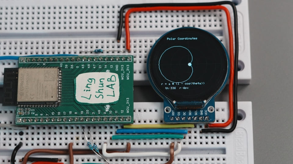
The round display draws a rotating cardioid curve in real time, overlaid on a polar coordinate grid with a tracking point — like a tiny oscilloscope tracing out a mathematical curve. Zero flicker throughout, locked at a smooth 16fps.
Component Overview
GC9A01 1.28” Round TFT Display
The GC9A01 is the driver IC, and the round IPS panel is the actual screen — they’re soldered together on a tiny module. All you need to do is “feed” it image data over SPI, and it takes care of lighting up every pixel.
| Parameter | Value |
|---|---|
| Resolution | 240 × 240 pixels |
| Color depth | 16-bit RGB565, 65536 colors |
| Interface | 4-wire SPI, up to 80MHz |
| Operating voltage | 3.3V (connect directly to ESP32-S3, no level shifter needed) |
| Panel type | IPS, viewing angle close to 180° |
| Module size | ~36mm diameter |
Why choose this display: cheap ($1–2 USD), widely available, and the round form factor is a natural fit for gauge and clock projects. The 240×240 resolution is also just right for the ESP32-S3’s available memory.
BOM
| Component | Qty | Notes |
|---|---|---|
| ESP32-S3 dev board | 1 | Any version with SPI pins works |
| GC9A01 1.28” round display module | 1 | Confirm the module has a BL pin |
| Jumper wires | Several | Female-to-female or female-to-male, depending on your board’s pin headers |
Module Pin Descriptions
| GC9A01 Module Pin | Function |
|---|---|
| VCC | Power positive (3.3V) |
| GND | Power ground |
| SCL / CLK | SPI clock signal |
| SDA / MOSI | SPI data input (master → slave) |
| CS | Chip select — screen responds to SPI when LOW |
| DC | Data/Command select: HIGH = data, LOW = command |
| RST | Hardware reset, triggered by LOW |
| BL | Backlight control — must be HIGH for screen to light up |
Wiring
Tip: Wire one row at a time using the table below, and check off each connection as you go — this saves 80% of debugging time.
| GC9A01 Display | ESP32-S3 |
|---|---|
| VCC | 3.3V |
| GND | GND |
| SCL / CLK | GPIO12 |
| SDA / MOSI | GPIO11 |
| CS | GPIO9 |
| DC | GPIO10 |
| RST | GPIO18 |
| BL | GPIO7 (code-controlled) or connect directly to 3.3V |
Note: The BL (backlight) pin is easy to miss. If you forget it, the screen will stay black after powering on — it’s not a code issue, and the screen isn’t broken. Check this first. Some modules don’t expose a BL pin at all, which means it’s already tied to 3.3V internally on the module — in that case, you can ignore it.
Required Libraries
Open Arduino IDE → Tools → Manage Libraries, then search and install:
| Library | Author | Tested Version |
|---|---|---|
| Arduino_GFX_Library | moononournation | 1.6.5 |
Don’t install TFT_eSPI: Under ESP32 Core 3.x, TFT_eSPI’s macro definitions and DMA initialization conflict with the new ESP32 framework, causing compilation errors or crashes on boot. Arduino_GFX_Library was built from the ground up with modern C++ and memory canvas support — it’s currently the most hassle-free choice for display projects. (As of 2026-05-18)
Complete Code
/**
 * ESP32-S3 + GC9A01 1.28" Round Display — Polar Coordinate Animation Demo
 * Double-buffered zero-flicker, locked at 16fps
 * Wiring: SCL=GPIO12, SDA=GPIO11, CS=GPIO9, DC=GPIO10, RST=GPIO18, BL=GPIO7
 */

#include <Arduino_GFX_Library.h>

// ---------------------------------------------------
// Step 1: Manually add color macros
// Newer Arduino_GFX removed BLACK / WHITE global exports.
// Without this section, you'll get "BLACK was not declared in this scope"
// ---------------------------------------------------
#ifndef BLACK
#define BLACK       0x0000
#endif
#ifndef WHITE
#define WHITE       0xFFFF
#endif
#ifndef RED
#define RED         0xF800
#endif
#ifndef GREEN
#define GREEN       0x07E0
#endif
#ifndef BLUE
#define BLUE        0x001F
#endif
#ifndef YELLOW
#define YELLOW      0xFFE0
#endif
#ifndef CYAN
#define CYAN        0x07FF
#endif
#ifndef MAGENTA
#define MAGENTA     0xF81F
#endif
#ifndef GRAY
#define GRAY        0x8410
#endif
#ifndef DARKGRAY
#define DARKGRAY    0x2104
#endif

// ---------------------------------------------------
// Step 2: Define color scheme (dark blue background + orange-red primary)
// ---------------------------------------------------
#define COLOR_BG        0x1123   // Dark blue-black background
#define COLOR_GRID      0x19E5   // Blue-gray grid
#define COLOR_PRIMARY   0xE73C   // Orange-red curve
#define COLOR_ACCENT    0xFDE0   // Golden-yellow radius line
#define COLOR_TEXT      0xF7BE   // Light gray text

// ---------------------------------------------------
// Step 3: Define physical pins
// ---------------------------------------------------
#define TFT_SCK  12
#define TFT_SDA  11
#define TFT_CS    9
#define TFT_DC   10
#define TFT_RST  18
#define TFT_BL    7

// ---------------------------------------------------
// Step 4: Instantiate SPI bus and display driver
// ---------------------------------------------------
Arduino_DataBus *bus = new Arduino_ESP32SPI(
    TFT_DC, TFT_CS, TFT_SCK, TFT_SDA, GFX_NOT_DEFINED /* MISO not needed */
);

Arduino_GFX *gfx = new Arduino_GC9A01(
    bus, TFT_RST,
    0,    /* Rotation angle */
    true  /* IPS display */
);

// ---------------------------------------------------
// Step 5: Allocate double-buffered canvas (240×240×2 Bytes = 115.2KB SRAM)
// All drawing happens in memory first, then flushes to the screen in one go — eliminates flicker
// ---------------------------------------------------
Arduino_Canvas *canvas = new Arduino_Canvas(240, 240, gfx);

// ---------------------------------------------------
// Animation variables
// ---------------------------------------------------
float angle = 0.0f;
const float  a_scale    = 50.0f;  // Cardioid scale factor (in pixels)
const int16_t cx        = 120;    // Center X
const int16_t cy        = 120;    // Center Y

unsigned long lastFrameTime = 0;
const int frameDelay = 1000 / 16; // Lock at 16fps

// Feature toggles (set to false to disable individual layers)
const bool showGrid     = true;
const bool showCurve    = true;
const bool showRadius   = true;
const bool showTelemetry= true;

void setup() {
    Serial.begin(115200);

    // Initialize display driver
    gfx->begin();

    // Turn on backlight (skip this = black screen)
    pinMode(TFT_BL, OUTPUT);
    digitalWrite(TFT_BL, HIGH);

    // Initialize double-buffered canvas
    if (!canvas->begin()) {
        Serial.println("Canvas memory allocation failed! Falling back to direct write (will flicker)");
    } else {
        Serial.println("Double buffer initialized. Zero-flicker rendering ready.");
    }
}

void loop() {
    // Frame rate limiter
    unsigned long now = millis();
    if (now - lastFrameTime < frameDelay) return;
    lastFrameTime = now;

    // Clear frame
    canvas->fillScreen(COLOR_BG);

    // --- Layer 1: Polar coordinate grid ---
    if (showGrid) {
        canvas->drawCircle(cx, cy,  30, COLOR_GRID);
        canvas->drawCircle(cx, cy,  60, COLOR_GRID);
        canvas->drawCircle(cx, cy,  90, COLOR_GRID);
        canvas->drawCircle(cx, cy, 110, COLOR_GRID);
        canvas->drawFastHLine(10, cy, 220, COLOR_GRID);
        canvas->drawFastVLine(cx, 10, 220, COLOR_GRID);
    }

    // --- Layer 2: Full cardioid trace r = a*(1 - cos θ) ---
    if (showCurve) {
        int16_t lx = 0, ly = 0;
        for (int16_t deg = 0; deg <= 360; deg += 3) {
            float rad = deg * DEG_TO_RAD;
            float r   = a_scale * (1.0f - cos(rad));
            int16_t x = cx + (int16_t)(r * cos(rad));
            int16_t y = cy - (int16_t)(r * sin(rad)); // Screen Y-axis points down, so negate
            if (deg > 0) canvas->drawLine(lx, ly, x, y, COLOR_PRIMARY);
            lx = x; ly = y;
        }
    }

    // --- Layer 3: Current tracking point & radius line ---
    float rad_a  = angle * DEG_TO_RAD;
    float active_r = a_scale * (1.0f - cos(rad_a));
    int16_t px = cx + (int16_t)(active_r * cos(rad_a));
    int16_t py = cy - (int16_t)(active_r * sin(rad_a));

    if (showRadius) canvas->drawLine(cx, cy, px, py, COLOR_ACCENT);
    canvas->fillCircle(px, py, 5, COLOR_TEXT);

    // --- Layer 4: Numeric readout ---
    if (showTelemetry) {
        canvas->setTextColor(COLOR_TEXT);
        canvas->setTextSize(1);
        canvas->setCursor(50, 25);
        canvas->print("Polar Coordinates");
        canvas->setCursor(28, 185);
        canvas->print("r = a * (1 - cos(theta))");
        canvas->setCursor(40, 200);
        canvas->print("th:"); canvas->print((int)angle);
        canvas->print("  r:"); canvas->print((int)active_r);
        canvas->print("px");
    }

    // Angle step (+6° per frame, one full revolution ≈ 1 second)
    angle += 6.0f;
    if (angle >= 360.0f) angle -= 360.0f;

    // Flush the in-memory canvas to the physical screen in one shot
    canvas->flush();
}
Code Walkthrough
Double-buffering mechanism: All drawing operations happen on the canvas (in memory). Only the final canvas->flush() call sends the complete frame to the physical screen. Instead of erasing the blackboard and then writing on it (which causes visible flicker), this is like writing everything on scratch paper first, then pasting the whole sheet up at once — the screen never sees a “half-drawn” state, so flicker is eliminated entirely.
Cardioid equation r = a * (1 - cos θ): This is a polar coordinate equation where r is the distance from the center and θ is the angle. By computing (r, θ) for each value of θ, converting to screen XY coordinates, and connecting the points, you get that heart-shaped curve.
Frame rate lock: frameDelay = 1000 / 16 sets the minimum frame interval to approximately 62ms. To speed up the animation, increase the += 6.0f step value; for smoother motion, raise targetFPS to 30 (though it will use more CPU).
Partition scheme: In Arduino IDE → Tools → Partition Scheme, select Huge APP (3MB No OTA). The 115KB canvas needs sufficient SRAM, and the default partition occasionally runs into heap space limitations.
Troubleshooting
Don’t panic — 90% of issues come from these common causes:
Screen stays black after power-on, no serial errors
Check the BL pin first — the backlight not being driven HIGH is the most common cause. Confirm that GPIO7 is executing digitalWrite(TFT_BL, HIGH), or connect the BL jumper directly to 3.3V to rule out a code issue.
Screen lights up but shows all white / all red / garbled pixels
SPI wiring is wrong. CS and DC are the easiest to swap (both are control lines that look similar). Double-check against the #define macros in the code (CS=GPIO9, DC=GPIO10) — trust the code, not the wiring table.
Compilation error: BLACK was not declared in this scope
You’re using Arduino_GFX version >= 1.3, which removed the global color macro exports. The #ifndef BLACK block at the top of the code must be kept — do not delete it.
Canvas memory allocation fails, serial reports falling back to direct write Available SRAM is less than 115KB. Check: ① Is the partition scheme set to Huge APP? ② Are there other large arrays consuming memory? ③ In rare cases, the dev board’s PSRAM isn’t enabled (enable it in the Board settings).
Animation stutters, doesn’t look like 16fps
Did you add a delay() inside loop()? If so, remove it — frame rate limiting is already handled via millis(), and combining both will double the frame interval.
FAQ
Q: Can I use different GPIO pins for CS and DC?
A: Yes. Just change the #define TFT_CS and #define TFT_DC at the top of the code — any free GPIO works. For SCL and SDA, it’s best to use hardware SPI pins (ESP32-S3 default SPI2: SCLK=12, MOSI=11) for maximum speed; using other pins will fall back to software SPI with noticeably lower performance.
Q: What refresh rates does the display support? A: The GC9A01’s SPI interface has a theoretical maximum clock of 80MHz, corresponding to a full-screen 240×240 refresh rate ceiling of about 40fps. This code locks at 16fps to preserve CPU headroom on mid-range ESP32-S3 modules. If your board runs at 240MHz, raising targetFPS to 30–40 should be fine.
Q: Can I drive two displays simultaneously?
A: Yes. Both displays share SCL/SDA, and you assign a separate CS pin to each. Instantiate two Arduino_GC9A01 objects and toggle CS to activate the respective display. Note the memory requirement: two canvases need 230KB SRAM combined, so PSRAM must be enabled.
Q: Should I power it with 3.3V or 5V? A: The GC9A01 module operates at 3.3V — connect it directly to the ESP32-S3’s 3.3V pin. Never connect 5V, as it will damage the driver IC.
Q: How do I display Chinese characters? A: Arduino_GFX_Library only includes built-in ASCII fonts by default. Displaying Chinese requires an additional font file (such as the U8g2 font library) or using the LVGL framework. Font files significantly increase Flash usage, so consider the LVGL + SPIFFS approach instead — I may cover this in a separate article.
Q: The GC9A01 display has no audio output capability — only display. How does this relate to I2S audio projects? A: It doesn’t. The GC9A01 is purely a display — its SPI interface only transmits image data. If you want to play audio simultaneously, you’ll need a separate I2S DAC module (like the MAX98357A). The two systems operate completely independently with no pin conflicts.
Ideas for Further Projects
- Analog clock face: Draw tick marks and hands, pair with a DS3231 RTC module for real-time display
- Rose curve mode: Change the equation to
r = a * sin(k * θ)— adjusting the parameter k changes the number of petals - Button-controlled animation switching: Three buttons to cycle through cardioid / rose curve / Lissajous figure modes
- ESP32 Wi-Fi integration: Pull weather API data and display temperature/humidity on a round gauge dashboard
- Dual round display setup: Buy two round screens and build a pair of matching animated displays