ESP32-S3 + GC9A01 Round Display + VL53L0X-V2 Laser ToF Gauge — Full Tutorial (SPI wiring + I2C pitfalls)
Drive a GC9A01 1.28-inch round display with an ESP32-S3 and pair it with a VL53L0X-V2 laser ToF sensor to build a cyberpunk-style laser ranging gauge with a live sweeping needle and a color-shifting arc. Includes a pitfall guide for SPI+I2C pin conflicts and the full Arduino source code.
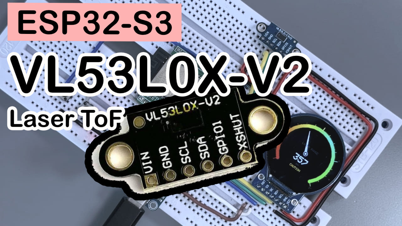
ESP32-S3 + GC9A01 Round Display + VL53L0X-V2 Laser Ranging: From Wiring to Lighting Up a Cyberpunk Gauge (Full Code Included)
Difficulty: ⭐⭐⭐☆☆ (a maker with a bit of experience can pull this off — you just need some patience with the jumpers) Estimated time: 45 minutes Tested with: Arduino IDE 2.3.8 + ESP32 Core 3.3.10 + Arduino_GFX_Library v1.6.5 + Adafruit_VL53L0X v1.2.5
TL;DR (quick start):
- Display wiring: GPIO12→SCL, GPIO11→SDA, GPIO9→CS, GPIO10→DC, GPIO18→RST, GPIO7→BL
- Sensor wiring: GPIO13→SDA, GPIO14→SCL (note: these are NOT the default I2C pins, because GPIO9 is already taken by the display’s CS)
- Install two libraries:
Arduino_GFX_Library,Adafruit_VL53L0X- Flash the “sensor test” sketch first — only flash the main program once you can see distance readings in the Serial Monitor
- Flash the main program — a laser ranging gauge with a sweeping needle and color-shifting arc appears on the round display
Why I built this round-display gauge
Plenty of people play with laser ranging (ToF) modules, but most stop at “print numbers to the Serial Monitor.” The goal of this project is dead simple: leverage the ESP32-S3’s performance and the GC9A01 round display’s visual appeal to turn abstract distance data into a high-refresh gauge that’s both practical and full of cyberpunk flavor.
The real challenge here isn’t the logic — it’s the pin conflict between the display’s SPI interface and the sensor’s I2C interface. To work around the dev board’s default pins “fighting each other” and breaking initialization, I remapped the hardware pins. Below is the full pitfall guide and the main program.
Result demo
Here’s the final effect: the round display draws an arc-shaped gauge that looks like a racing tachometer. The needle points in real time to the currently measured distance, and the arc color shifts from red (near/dangerous) to green (far/safe). The center shows the exact millimeter reading plus a status word (DANGER / WARNING / CAUTION / SAFE / CLEAR). Wave your hand in front of the sensor and the needle follows along in real time — honestly pretty satisfying to watch.
Component overview
The dev board (ESP32-S3) needs no introduction — let’s focus on the other two leads.
GC9A01 240×240 round display
The GC9A01 is a display driver chip purpose-built for round screens. Its job is to “translate” the pixel data you send into an actual image on the panel — you say what to draw, it handles how, taking care of all the refresh and scanning in between. You just call the API.
| Parameter | Value |
|---|---|
| Resolution | 240×240 |
| Size | 1.28 inch |
| Interface | SPI |
| Color depth | 65K colors (RGB565) |
| Driver library | Arduino_GFX_Library |
I picked it because it’s cheap, round screens look naturally great for gauges, and the SPI interface is fast enough that the needle sweeps with no smearing.
VL53L0X-V2 laser ranging sensor
The VL53L0X is a laser ranging sensor based on the time-of-flight (ToF) principle. In plain English: it fires out a burst of infrared laser light you can’t see, times how long the beam takes to bounce off an object and come back, and back-calculates the distance — same idea as a bat’s echolocation, except it uses light instead of sound.
| Parameter | Value |
|---|---|
| Measuring range | 30mm–1200mm (up to ~2000mm in long-distance mode) |
| Accuracy | ±3% |
| Interface | I2C (up to 400kHz) |
| Laser wavelength | 940nm (invisible to the human eye, Class 1 laser, safe) |
I chose it because readings aren’t affected by the target’s color or material (unfrared ranging barely cares about surface type, unlike ultrasonic), it’s tiny enough to fit into any enclosure, and I2C only needs two signal wires.
💡 Heads-up: this module usually ships without an optical cover (I forgot to buy one with mine, too)
Running it bare during development is totally fine, but there are a few gotchas worth knowing ahead of time:
- Don’t poke the chip surface with your finger: those two glass windows on the chip, smaller than a sesame seed (one emitter, one receiver), hate dust, oil, and moisture. Once dirty, stray dust scatters the laser back and causes “crosstalk” — readings mysteriously come up short, numbers jump around, and in severe cases the sensor just fails.
- If it does get dirty, don’t scrub it blindly: never wipe it with your shirt hem or a paper tissue (you’ll scratch it in one swipe). For dust, give it a blast with a rocket air blower; for oil, lightly dab a cotton swab with a tiny bit of anhydrous alcohol, gently wipe, and let it dry.
- It goes “blind” under strong light: sunlight and old incandescent bulbs contain infrared, so when you’re running it bare without a cover, the max range visibly shrinks. You’ll barely notice it on an indoor desktop, but keep that in mind if you take it outside.
If you plan to mount this in an enclosure long-term: never just slap ordinary clear tape or plain glass over the chip — ordinary materials reflect IR, and the sensor will mistake the cover for an obstacle and lock onto
0mmor a few centimeters. Either leave a hole so it pokes through, or properly buy a piece of 940nm IR-pass filter glass, and mount it as close as possible (gap under 1mm).
BOM (parts list)
| Part | Qty | Notes |
|---|---|---|
| ESP32-S3 dev board | 1 | Any model with enough GPIO will do |
| GC9A01 1.28“ round display (SPI) | 1 | Make sure it’s the SPI version, not the parallel version |
| VL53L0X-V2 ToF ranging module | 1 | Breadboard-friendly breakout |
| Dupont jumpers | a bunch |
Pinout reference
GC9A01 pins
| Pin | Function |
|---|---|
| VCC | Power positive, connect to 3.3V |
| GND | Power ground |
| SCL/CLK | SPI clock line |
| SDA/MOSI | SPI data line |
| CS | Chip select, active when LOW |
| DC | Data/command select pin |
| RST | Reset pin |
| BL | Backlight control pin (some modules don’t break this out — you can ignore it) |
VL53L0X-V2 pins
| Pin | Function |
|---|---|
| VIN | Power positive |
| GND | Power ground |
| SCL | I2C serial clock input |
| SDA | I2C serial data |
| GPIO1 | Interrupt output, signals data ready (not used here — leave floating) |
| XSHUT | Shutdown pin, pulled HIGH by default for normal operation, pulled LOW to shut down (not used here — leave floating) |
Wiring
I recommend wiring up row by row against the table below and checking each one off as you go — it’ll save you 80% of your debugging time.
ESP32-S3 to GC9A01 display
| GC9A01 display | ESP32-S3 |
|---|---|
| VCC | 3.3V |
| GND | GND |
| SCL / CLK | GPIO12 |
| SDA / MOSI | GPIO11 |
| CS | GPIO9 |
| DC | GPIO10 |
| RST | GPIO18 |
| BL | GPIO7 (code-controlled), or tie it straight to 3.3V (some dev boards have no separate backlight control) |
ESP32-S3 to VL53L0X-V2 sensor
| VL53L0X-V2 | ESP32-S3 |
|---|---|
| VIN | 3.3V |
| GND | GND |
| SDA | GPIO13 |
| SCL | GPIO14 |
| GPIO1 | leave floating, unconnected |
| XSHUT | leave floating (internally pulled HIGH) |
⚠️ Note: the ESP32-S3’s default I2C pins are usually GPIO8 (SDA) / GPIO9 (SCL), but in this project GPIO9 is already taken by the display’s CS, so the sensor’s I2C was manually moved to GPIO13/GPIO14. The code uses
Wire.begin(I2C_SDA, I2C_SCL)to specify those two pins — when wiring, do NOT take a shortcut and wire them back to the defaults, or the display and sensor will fight each other and neither will work.
Libraries to install
In the Arduino IDE, search and install via the Library Manager:
Arduino_GFX_Library(by moononournation) — tested passing version v1.6.5Adafruit_VL53L0X(by Adafruit) — tested passing version v1.2.5. During install it’ll prompt you to also installAdafruit BusIO— install that too.
IDE version: Arduino IDE 2.3.8, ESP32 board support package is 3.3.10. If your versions are too far off you may hit API incompatibilities — I recommend aligning them.
Full code
Gauge main program
/*
 * ═══════════════════════════════════════════════════════
 *  Cyber Gauge Dashboard
 *  Round GC9A01 (240×240) + VL53L0X-V2 laser ranging
 *  MCU: ESP32-S3
 *  Driver library: Arduino_GFX_Library v1.6.5
 * ═══════════════════════════════════════════════════════
 */

#include <Arduino.h>
#include <Wire.h>
#include <Adafruit_VL53L0X.h>
#include <Arduino_GFX_Library.h>

// ───────── Color definitions (Arduino_GFX v1.6.5 needs these defined manually) ─────────
#define BLACK       0x0000
#define WHITE       0xFFFF
#define RED         0xF800
#define GREEN       0x07E0
#define BLUE        0x001F
#define CYAN        0x07FF
#define YELLOW      0xFFE0
#define ORANGE      0xFD20
#define DARKGREY    0x4208
#define LIGHTGREY   0xC618

// Cyber theme colors
#define CYBER_BG      0x0841    // Deep background
#define CYBER_PANEL   0x1082    // Panel color
#define CYBER_BLUE    0x06DF    // Neon blue
#define CYBER_CYAN    0x07F5    // Neon cyan
#define CYBER_GREEN   0x47E0    // Neon green
#define CYBER_RED     0xF806    // Warning red
#define CYBER_ORANGE  0xFB40    // Orange
#define CYBER_YELLOW  0xFF80    // Yellow
#define CYBER_DIM     0x4A49    // Dim color

// ───────── Pin definitions ─────────
#define TFT_SCK   12
#define TFT_MOSI  11
#define TFT_CS    9
#define TFT_DC    10
#define TFT_RST   18
#define TFT_BL    7

// VL53L0X runs on its own I2C bus to avoid GPIO9 (taken by TFT_CS)
#define I2C_SDA   13
#define I2C_SCL   14

// ───────── Screen dimensions ─────────
#define SCREEN_W  240
#define SCREEN_H  240
#define CX        120     // Center X
#define CY        120     // Center Y

// ───────── Gauge parameters ─────────
#define GAUGE_R       95      // Scale arc radius
#define GAUGE_WIDTH   10      // Arc thickness
#define NEEDLE_LEN    78      // Needle length
#define START_ANGLE   135     // Start angle (degrees)
#define END_ANGLE     405     // End angle (degrees)
#define MAX_DIST      800     // Max display distance (mm)
#define MIN_DIST      20      // Min distance (mm)
#define TICK_COUNT    16      // Number of ticks

// ───────── Global objects ─────────
Arduino_DataBus *bus = new Arduino_ESP32SPI(
  TFT_DC, TFT_CS, TFT_SCK, TFT_MOSI, -1 /* MISO */
);

Arduino_GFX *gfx = new Arduino_GC9A01(
  bus, TFT_RST, 0 /* rotation */, true /* IPS */
);

Adafruit_VL53L0X lox = Adafruit_VL53L0X();
Arduino_Canvas *canvas;   // Off-screen canvas to eliminate flicker

// ───────── State variables ─────────
float currentAngle = START_ANGLE;
float targetAngle  = START_ANGLE;
int   currentDist  = 0;
int   lastDist     = -1;

// ═══════════════════════════════════════
//  Utility functions
// ═══════════════════════════════════════

// RGB565 color blending
uint16_t blendColor(uint16_t c1, uint16_t c2, float t) {
  uint8_t r1 = (c1 >> 11) & 0x1F, g1 = (c1 >> 5) & 0x3F, b1 = c1 & 0x1F;
  uint8_t r2 = (c2 >> 11) & 0x1F, g2 = (c2 >> 5) & 0x3F, b2 = c2 & 0x1F;
  uint8_t r = r1 + (r2 - r1) * t;
  uint8_t g = g1 + (g2 - g1) * t;
  uint8_t b = b1 + (b2 - b1) * t;
  return (r << 11) | (g << 5) | b;
}

// Get color from distance (near = red, far = green)
uint16_t getDistColor(int dist) {
  float ratio = constrain((float)dist / MAX_DIST, 0.0, 1.0);
  if (ratio < 0.15)  return CYBER_RED;
  if (ratio < 0.30)  return blendColor(CYBER_RED, CYBER_ORANGE, (ratio - 0.15) / 0.15);
  if (ratio < 0.50)  return blendColor(CYBER_ORANGE, CYBER_YELLOW, (ratio - 0.30) / 0.20);
  if (ratio < 0.70)  return blendColor(CYBER_YELLOW, CYBER_CYAN, (ratio - 0.50) / 0.20);
  return blendColor(CYBER_CYAN, CYBER_GREEN, (ratio - 0.70) / 0.30);
}

// Get status text
const char* getStatusText(int dist) {
  if (dist < 100) return "DANGER";
  if (dist < 200) return "WARNING";
  if (dist < 400) return "CAUTION";
  if (dist < 600) return "SAFE";
  return "CLEAR";
}

// ═══════════════════════════════════════
//  Drawing functions
// ═══════════════════════════════════════

// Draw a thick arc (simulated with many short segments)
void drawArc(Arduino_Canvas *c, int cx, int cy, int r,
             float startDeg, float endDeg, int thickness,
             uint16_t color) {
  float step = 1.5;  // Angle step
  for (float a = startDeg; a <= endDeg; a += step) {
    float rad = a * DEG_TO_RAD;
    int x = cx + cos(rad) * r;
    int y = cy + sin(rad) * r;
    c->fillCircle(x, y, thickness / 2, color);
  }
}

// Draw a gradient arc
void drawGradientArc(Arduino_Canvas *c, int cx, int cy, int r,
                     float startDeg, float endDeg, int thickness) {
  float totalAngle = endDeg - startDeg;
  float step = 1.5;

  for (float a = startDeg; a <= endDeg; a += step) {
    float ratio = (a - startDeg) / totalAngle;
    uint16_t color;

    // Red -> orange -> yellow -> cyan -> green
    if (ratio < 0.2)       color = blendColor(CYBER_RED, CYBER_ORANGE, ratio / 0.2);
    else if (ratio < 0.4)  color = blendColor(CYBER_ORANGE, CYBER_YELLOW, (ratio - 0.2) / 0.2);
    else if (ratio < 0.6)  color = blendColor(CYBER_YELLOW, CYBER_CYAN, (ratio - 0.4) / 0.2);
    else                   color = blendColor(CYBER_CYAN, CYBER_GREEN, (ratio - 0.6) / 0.4);

    float rad = a * DEG_TO_RAD;
    int x = cx + cos(rad) * r;
    int y = cy + sin(rad) * r;
    c->fillCircle(x, y, thickness / 2, color);
  }
}

// Draw tick marks
void drawTicks(Arduino_Canvas *c) {
  float totalAngle = END_ANGLE - START_ANGLE;

  for (int i = 0; i <= TICK_COUNT; i++) {
    float angle = START_ANGLE + (float)i / TICK_COUNT * totalAngle;
    float rad = angle * DEG_TO_RAD;
    float ratio = (float)i / TICK_COUNT;

    // Tick color
    uint16_t color;
    if (ratio < 0.2)       color = CYBER_RED;
    else if (ratio < 0.4)  color = CYBER_ORANGE;
    else if (ratio < 0.6)  color = CYBER_YELLOW;
    else if (ratio < 0.8)  color = CYBER_CYAN;
    else                   color = CYBER_GREEN;

    // Major / minor ticks
    bool isMajor = (i % 4 == 0);
    int innerR  = GAUGE_R + 4;
    int outerR  = innerR + (isMajor ? 12 : 6);
    int thick   = isMajor ? 2 : 1;

    int x1 = CX + cos(rad) * innerR;
    int y1 = CY + sin(rad) * innerR;
    int x2 = CX + cos(rad) * outerR;
    int y2 = CY + sin(rad) * outerR;

    // Draw the tick line
    for (int t = 0; t < thick; t++) {
      c->drawLine(x1 + t, y1, x2 + t, y2, color);
    }

    // Number labels on major ticks
    if (isMajor) {
      int labelR = outerR + 12;
      int lx = CX + cos(rad) * labelR;
      int ly = CY + sin(rad) * labelR;
      int val = (float)i / TICK_COUNT * MAX_DIST;

      c->setTextColor(CYBER_DIM);
      c->setTextSize(1);
      c->setCursor(lx - 8, ly - 4);
      c->print(val);
    }
  }
}

// Draw the needle
void drawNeedle(Arduino_Canvas *c, float angleDeg, uint16_t color) {
  float rad = angleDeg * DEG_TO_RAD;

  // Needle tip
  int tipX = CX + cos(rad) * NEEDLE_LEN;
  int tipY = CY + sin(rad) * NEEDLE_LEN;

  // Needle base (two points perpendicular to the needle direction)
  float perpRad = rad + PI / 2;
  int baseW = 4;
  int bx1 = CX + cos(perpRad) * baseW;
  int by1 = CY + sin(perpRad) * baseW;
  int bx2 = CX - cos(perpRad) * baseW;
  int by2 = CY - sin(perpRad) * baseW;

  // Draw the triangular needle
  c->fillTriangle(tipX, tipY, bx1, by1, bx2, by2, color);

  // Center decorative hub
  c->fillCircle(CX, CY, 7, CYBER_PANEL);
  c->drawCircle(CX, CY, 7, color);
  c->fillCircle(CX, CY, 3, color);
}

// Draw the full dashboard
void drawDashboard(int dist) {
  canvas->fillScreen(CYBER_BG);

  // Outer decorative ring
  canvas->drawCircle(CX, CY, 118, CYBER_PANEL);

  // Background arc (dim track)
  drawArc(canvas, CX, CY, GAUGE_R,
          START_ANGLE, END_ANGLE, GAUGE_WIDTH, CYBER_PANEL);

  // Gradient arc (full)
  drawGradientArc(canvas, CX, CY, GAUGE_R,
                  START_ANGLE, END_ANGLE, GAUGE_WIDTH);

  // Ticks
  drawTicks(canvas);

  // Compute needle angle
  float ratio = constrain((float)dist / MAX_DIST, 0.0, 1.0);
  targetAngle = START_ANGLE + ratio * (END_ANGLE - START_ANGLE);

  // Smooth interpolation
  currentAngle += (targetAngle - currentAngle) * 0.15;

  // Pick the color
  uint16_t needleColor = getDistColor(dist);

  // Draw the needle
  drawNeedle(canvas, currentAngle, WHITE);

  // ── Central readout area ──
  // Distance value
  canvas->setTextColor(WHITE);
  canvas->setTextSize(3);
  String distStr = String(dist);
  int textW = distStr.length() * 18;
  canvas->setCursor(CX - textW / 2, CY + 16);
  canvas->print(distStr);

  // Unit
  canvas->setTextColor(CYBER_DIM);
  canvas->setTextSize(1);
  canvas->setCursor(CX - 6, CY + 42);
  canvas->print("mm");

  // Title
  canvas->setTextColor(CYBER_DIM);
  canvas->setTextSize(1);
  canvas->setCursor(CX - 30, CY - 28);
  canvas->print("LASER RANGE");

  // Status indicator
  canvas->setTextColor(needleColor);
  canvas->setTextSize(1);
  const char* status = getStatusText(dist);
  int sLen = strlen(status);
  canvas->setCursor(CX - sLen * 3, CY + 56);
  canvas->print(status);

  // Push to the screen
  canvas->flush();
}

// ═══════════════════════════════════════
//  setup() & loop()
// ═══════════════════════════════════════

void setup() {
  Serial.begin(115200);
  Serial.println("\n═══ Cyber Gauge Dashboard ═══");

  // Step 1: turn on the backlight
  pinMode(TFT_BL, OUTPUT);
  digitalWrite(TFT_BL, HIGH);

  // Step 2: initialize the display
  gfx->begin();
  gfx->fillScreen(BLACK);
  gfx->setRotation(0);

  // Step 3: create the off-screen canvas (double buffering to prevent flicker)
  canvas = new Arduino_Canvas(SCREEN_W, SCREEN_H, gfx);
  canvas->begin();

  // Boot splash
  canvas->fillScreen(CYBER_BG);
  canvas->setTextColor(CYBER_BLUE);
  canvas->setTextSize(2);
  canvas->setCursor(40, 100);
  canvas->print("CYBER");
  canvas->setCursor(40, 125);
  canvas->print("GAUGE");
  canvas->setTextColor(CYBER_DIM);
  canvas->setTextSize(1);
  canvas->setCursor(55, 160);
  canvas->print("Booting...");
  canvas->flush();

  delay(1000);

  // Step 4: initialize I2C and the sensor (note: custom pins, not the defaults)
  Wire.begin(I2C_SDA, I2C_SCL);

  if (!lox.begin()) {
    Serial.println("VL53L0X init failed!");
    canvas->fillScreen(CYBER_BG);
    canvas->setTextColor(CYBER_RED);
    canvas->setTextSize(1);
    canvas->setCursor(50, 110);
    canvas->print("SENSOR ERROR");
    canvas->setCursor(40, 130);
    canvas->print("Check wiring!");
    canvas->flush();
    while (1) delay(100);
  }

  Serial.println("VL53L0X ready ✓");

  // Step 5: start continuous ranging mode
  lox.startRangeContinuous();

  Serial.println("Gauge dashboard started!");
}

void loop() {
  // Read the distance
  if (lox.isRangeComplete()) {
    int dist = lox.readRange();

    // Filter out invalid values
    if (dist > 0 && dist < 8190) {
      // Simple smoothing filter to keep the numbers from jittering
      currentDist = currentDist * 0.7 + dist * 0.3;
      currentDist = constrain(currentDist, MIN_DIST, MAX_DIST);

      // Only redraw when the distance changes beyond a threshold — saves CPU
      if (abs(currentDist - lastDist) > 2) {
        drawDashboard(currentDist);
        lastDist = currentDist;

        Serial.printf("Distance: %d mm\n", currentDist);
      }
    }
  }

  delay(30);  // ~33 FPS
}
Sensor test sketch (recommended: run this first)
Before flashing the main program, I strongly recommend flashing this minimal sketch to confirm the sensor works on its own — that way, if something’s wrong it’s much easier to troubleshoot than digging through a pile of drawing code.
/*
 *  Test the VL53L0X sensor
 */

#include <Wire.h>
#include <Adafruit_VL53L0X.h>

#define I2C_SDA  13
#define I2C_SCL  14

Adafruit_VL53L0X lox = Adafruit_VL53L0X();

void setup() {
  Serial.begin(115200);
  delay(1000);
  Serial.println("VL53L0X sensor test");

  Wire.begin(I2C_SDA, I2C_SCL);

  if (!lox.begin()) {
    Serial.println("❌ Sensor not found, check wiring!");
    while (1);
  }

  Serial.println("✓ Sensor ready, starting measurements...");
  lox.startRangeContinuous();
}

void loop() {
  if (lox.isRangeComplete()) {
    int dist = lox.readRange();
    Serial.printf("Distance: %d mm\n", dist);
  }
  delay(100);
}
Code walkthrough
A few spots that tend to make people’s eyes glaze over — let’s pull those out:
blendColor(): blends two RGB565 colors by a ratiot. This is what produces the red→orange→yellow→cyan→green gradient arc — rather than abruptly switching colors, it looks smooth.Arduino_Canvas(off-screen canvas): all drawing happens first on an in-memory canvas, then a singleflush()pushes it to the screen — instead of drawing stroke by stroke directly to the panel. Without this, the needle sweep would show obvious flicker and tearing.- Smoothing filter
currentDist * 0.7 + dist * 0.3: raw sensor readings jitter slightly. This is a simple first-order low-pass filter that makes the needle sweep more smoothly instead of twitching nervously. I2C_SDA=13, I2C_SCL=14: the trap I kept stressing in the wiring section — let me bang the drum once more. These are NOT the ESP32-S3’s default I2C pins. They were moved manually because the default GPIO9 is taken by the display’s CS.
Troubleshooting
Don’t panic — 80% of the issues come down to these:
-
The screen stays black after flashing First check whether
TFT_BL(backlight) is wired correctly, and whetherdigitalWrite(TFT_BL, HIGH)in the code actually executed. Then check whether the RST pin has a loose contact — a loose RST is the most common cause of a black round display. -
The Serial Monitor prints “VL53L0X init failed!” 99% of the time it’s a wiring issue: confirm VIN/GND aren’t swapped, that SDA/SCL really are on GPIO13/GPIO14 (not the default GPIO8/9), and that your Dupont jumpers aren’t loose. You can run the “sensor test” sketch on its own to rule out interference from the display.
-
The display lights up, but shows garbage / stripes / wrong colors Most likely the SPI clock or data line has a poor contact, or your Dupont jumpers are too long and the signal is degrading. Check that SCL/SDA map to GPIO12/GPIO11, and keep the jumpers under 15cm.
-
The needle jumps wildly and the numbers keep changing This is either an underpowered smoothing factor or a reflective/transparent object in front of the sensor interfering. Try changing the weights in
currentDist * 0.7 + dist * 0.3to0.85/0.15for stronger filtering (at the cost of slower response). -
Compile error: can’t find
Adafruit_VL53L0X.horArduino_GFX_Library.hThat means the libraries aren’t installed correctly — go to the Library Manager, search for the exact library name and reinstall. Be careful not to install a same-named third-party fork by mistake. -
The needle angle and tick numbers don’t line up Check whether
MAX_DISTwas turned down but the tick labels weren’t updated to match — the two have to stay consistent, or the tick numbers and the actual needle position will be offset.
FAQ
Q: What are the ESP32-S3’s default I2C pins? A: Usually GPIO8 (SDA) and GPIO9 (SCL), but in this project GPIO9 is taken by the display’s CS, so the sensor’s I2C was moved to GPIO13/GPIO14.
Q: How far can the VL53L0X measure, and how accurate is it? A: The official effective range is about 30mm–1200mm (up to 2000mm in long-distance mode), with accuracy around ±3%.
Q: Does the GC9A01 round display support touch? A: The GC9A01 itself is just a display driver chip and doesn’t include touch. Some modules on the market integrate a capacitive touch chip separately — confirm the exact model you’re buying has a touch version before purchasing.
Q: Will the VL53L0X laser hurt my eyes? A: No. It’s a Class 1 laser product, the 940nm wavelength is invisible to the human eye, and the power is extremely low — it meets eye-safety standards, so normal use is nothing to worry about.
Q: The GC9A01 screen doesn’t light up, but power is fine — what’s going on? A: The most common cause is a poor contact on the RST (reset) pin, or the backlight BL pin not being pulled HIGH. Check those two spots first.
Q: Why does the code use the off-screen canvas Arduino_Canvas instead of drawing straight to the screen?
A: Drawing directly to the screen causes visible flicker and tearing when the needle moves and the arc redraws. Using a canvas as a double buffer and flushing it all at once keeps the picture clean and crisp.
Q: Is there any difference between VL53L0X-V2 and the regular VL53L0X? A: The core ranging principle and pinout are identical. The V2 is usually a revision made by the module vendor on the PCB design and voltage regulator circuit. For specific differences, refer to the documentation that comes with the module you bought.
Q: Is USB power enough for this ESP32-S3 project? A: Yes. The display and sensor together draw little power, so a normal USB 5V/500mA supply is more than enough.
Going further
- Add a buzzer that alarms when the distance enters the DANGER zone — instant DIY parking radar
- Log the historical distance data and plot a real-time curve to track object movement
- Add two push buttons to switch the display unit (mm / cm / inch)
- Build an enclosure that suction-cups to the windshield and actually use it as a backup radar