ESP32-S3 + GC9A01 + HMC5883L Round Display Compass — It Works, It Looks Great, But the Accuracy… You Know (Full Tutorial)
Difficulty: ⭐⭐⭐☆☆ (Some basics needed, but approachable) Estimated Time: 45 minutes Test Environment: Arduino IDE 2.3.8 · Arduino_GFX_Library v1.6.5 · Adafruit_HMC5883_U v1.2.4
⚠️ Bottom line upfront: The compass built with this setup looks impressive and gets the general direction right, but typical accuracy is in the ±5°~±15° range, heavily affected by nearby magnetic fields. It’s perfectly fine for learning driver workflows, doing demos, or using as a desk ornament. For outdoor navigation, drone orientation, or any application requiring strict accuracy — not recommended. I’ll explain why below.
TL;DR (Quick Start):
- Run an I2C scan first to confirm the chip address —
0x0Dmeans QMC5883L (clone),0x1Emeans genuine HMC5883L. Install the matching library, otherwise all readings will be garbage.- Wire up 12 connections per the wiring table (8 for the display + 4 for the sensor; 3.3V/GND can be shared).
- Change
DECLINATION_DEGto your city’s magnetic declination (Beijing ≈ -6.5°, Tokyo ≈ -7.5°, link to lookup tool at the end).- Hold the BOOT button (GPIO0) during power-on to enter 15-second rotation calibration — slowly rotate the device one full circle while keeping it level.
- Release the button and calibration data is automatically saved to NVS — it survives power loss, so next time just turn it on and go.
Introduction
When I bought this GC9A01 round display, I stared at it for a while — 1.28 inches, 240×240, a perfect circle. Isn’t this a natural compass dial just waiting to happen?
So I spent a weekend building it, fired it up, compared it to my phone’s compass… well, the needle was pointing in the right general direction, just off by a bit — maybe ten degrees or so. After spinning it a couple more times, I noticed it stopped responding. Power cycled it, and it still wouldn’t really move…
“I must not have calibrated it properly.” I recalibrated, moved to a different spot, compared against my iPhone — the gap was still there. It wasn’t a code bug; it was the inherent limitation of this sensor module. I could observe that bringing my phone close also affected it.
So this article has two goals: first, to build the round display compass completely — code that runs, calibration that works, and results that genuinely look great. Second, to be transparent about the accuracy limitations, so you know where the “gotchas” are before you start — rather than discovering after everything is built that the needle doesn’t match Google Maps.
If you want to learn how to drive a GC9A01 + HMC5883L, or build a cool desk gadget, this project is absolutely worth doing. If your goal is “navigation-grade accuracy,” I’d suggest jumping straight to the “Is It Suitable for Real Projects?” section later in this article before deciding whether to continue.
Demo
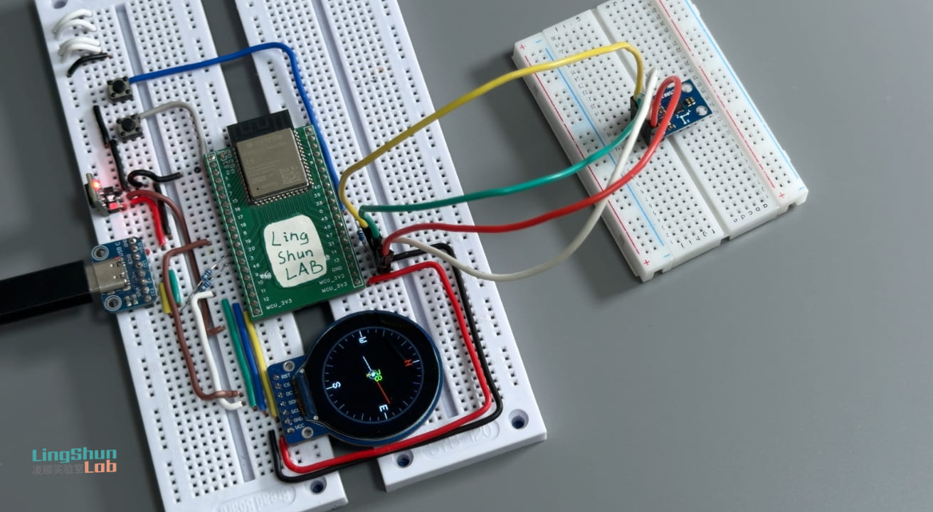
The GC9A01 round display shows a real-time compass dial: a red needle points north, the center displays the current heading in green digits (0°~359°), and yellow letters indicate the nearest eight-point direction (N / NE / E / SE / S / SW / W / NW). Hold the BOOT button during power-on to enter a 15-second rotation calibration mode, where the screen shows a progress bar and real-time magnetic field range. After calibration, the needle moves smoothly at approximately 25fps, without the jittery behavior seen when uncalibrated.
About accuracy, let’s be clear: A calibrated HMC5883L in an ideal environment (away from metal and other magnetic sources) has a heading error of about ±5°. Near a computer chassis, charger, speaker, or screwdriver, the error easily climbs to ±15° or more. For everyday desktop use, “the general direction is right,” but I’m not sure if the module I bought is genuine — sometimes it just stops responding. Don’t expect accuracy down to individual degrees. This is an inherent hardware limitation, not a code issue. The “Is It Suitable for Real Projects?” section later explains this in detail.
Component Overview
GC9A01 Round TFT Display
Imagine a circular watch display about 3.2 cm in diameter — that’s the GC9A01. SPI interface, 240×240 resolution, driver built into the display controller. ESP32 pushes pixels directly without needing external RAM. I chose it for two reasons: the round shape is naturally suited for a compass UI, and Arduino_GFX_Library has full support, making the driver code just a few lines.
| Parameter | Specification |
|---|---|
| Resolution | 240 × 240 px |
| Interface | SPI (up to 80 MHz) |
| Power Supply | 3.3V |
| Backlight Control | HIGH to turn on |
| Typical Current Draw | ~20 mA (full brightness) |
GC9A01 Display Module (8 pins)
| Pin Label | Function |
|---|---|
| VCC | 3.3V power supply |
| GND | Ground |
| SCL / CLK | SPI clock |
| SDA / MOSI | SPI data (master→slave) |
| CS | Chip select, active LOW |
| DC | Data/command select |
| RST | Hardware reset, active LOW |
| BL | Backlight control, HIGH to turn on |
HMC5883L / QMC5883L 3-Axis Magnetometer
The magnetometer is the compass’s “nose” — it senses the strength of Earth’s magnetic field in the X/Y/Z directions, then uses inverse trigonometric functions to calculate which direction you’re facing. I2C interface, 3.3V power supply, each reading takes only a few milliseconds.
Important note: the vast majority of modules sold as “HMC5883L” actually use QST’s QMC5883L chip — the two are pin-compatible but have completely different register sets and require different driver libraries. Don’t rush to install a library. Follow the I2C scan steps below to confirm which chip you have, then install the matching library — this will save you most of your troubleshooting time.
| Parameter | HMC5883L (Original) | QMC5883L (Clone) |
|---|---|---|
| I2C Address | 0x1E | 0x0D |
| Measurement Range | ±8 Gauss | ±8 Gauss |
| Resolution | 2 mGauss | 2 mGauss |
| Noise Density | ~2 mGauss/√Hz | ~2 mGauss/√Hz |
HMC5883L / QMC5883L Magnetometer Module (4 commonly used pins)
| Pin Label | Function |
|---|---|
| VCC | 3.3V power supply |
| GND | Ground |
| SDA | I2C data |
| SCL | I2C clock |
| DRDY | Data-ready interrupt (not used in this project, can be left unconnected) |
Both chips have similar baseline performance and work fine for experiments and demos. But to be transparent: neither chip at this price point has on-chip temperature drift compensation or sensor fusion — they only do basic 2D magnetic field measurement. This determines their accuracy ceiling and also means they’re only suitable for demos and learning, not real navigation applications.
BOM
| Component | Model / Spec | Qty | Reference Price |
|---|---|---|---|
| MCU dev board | ESP32-S3 (any dev board) | 1 | ¥25~40 |
| Round TFT display | GC9A01, 1.28”, 240×240 | 1 | ¥12~20 |
| Magnetometer module | HMC5883L or QMC5883L | 1 | ¥3~8 |
| Dupont wires | Male-to-female, 20cm | Several | ¥3 |
Wiring
After wiring, double-check each connection against the table. This step alone eliminates 80% of “why isn’t it working” troubleshooting time.
GC9A01 Round Display → ESP32-S3
| Display Pin | ESP32-S3 |
|---|---|
| VCC | 3.3V |
| GND | GND |
| SCL / CLK | GPIO12 |
| SDA / MOSI | GPIO11 |
| CS | GPIO9 |
| DC | GPIO10 |
| RST | GPIO18 |
| BL | GPIO7 (or connect directly to 3.3V for always-on) |
HMC5883L / QMC5883L → ESP32-S3
| Sensor Pin | ESP32-S3 |
|---|---|
| VCC | 3.3V |
| GND | GND |
| SDA | GPIO14 |
| SCL | GPIO13 |
Required Libraries
Before installing libraries, do one thing first — confirm your magnetometer chip model. Upload the code below, open the Serial Monitor (115200 baud), and check the printed I2C address:
#include <Wire.h>

void setup() {
  Serial.begin(115200);
  Wire.begin(13, 14);  // SDA=13, SCL=14, matching this project

  Serial.println("Scanning I2C...");
  for (uint8_t addr = 1; addr < 127; addr++) {
    Wire.beginTransmission(addr);
    if (Wire.endTransmission() == 0) {
      Serial.printf("Found device at 0x%02X\n", addr);
    }
  }
  Serial.println("Done.");
}

void loop {}- Prints
0x1E→ genuine HMC5883L, install Adafruit HMC5883 Unified (by Adafruit) - Prints
0x0D→ QMC5883L, you need to swap the#includeand sensor object in the code to the matching library (see FAQ #3)
Once you’ve confirmed the chip, open Arduino IDE → Library Manager, search and install:
| Library | Applicable Chip | Tested Version |
|---|---|---|
| Arduino_GFX_Library | — | v1.6.5 |
| Adafruit HMC5883 Unified | HMC5883L (0x1E) | v1.2.4 |
| Adafruit Unified Sensor | Required for both | v1.1.15 |
If you have QMC5883L (0x0D), see the alternative approach in the FAQ section.
Complete Code
#include <Arduino_GFX_Library.h>
#include <Wire.h>
#include <Adafruit_Sensor.h>
#include <Adafruit_HMC5883_U.h>
#include <Preferences.h>
#include <math.h>

// --- Step 1: Pin Definitions ---
#define TFT_SCK  12
#define TFT_MOSI 11
#define TFT_CS    9
#define TFT_DC   10
#define TFT_RST  18
#define TFT_BL    7
#define I2C_SDA  14
#define I2C_SCL  13

// Hold this button during power-on to enter calibration mode (BOOT button, GPIO0, no external button needed)
#define CAL_BTN   0

// Magnetic declination (negative = west) — Lookup tool: https://www.ngdc.noaa.gov/geomag/calculators/magcalc.shtml
// Beijing ≈ -6.5°, Shanghai ≈ -5.5°, Guangzhou ≈ -3°, Tokyo ≈ -7.5°
// If you don't change this value, the compass will be offset by X degrees overall — all directions will be wrong
#define DECLINATION_DEG  (-3.0f)

// --- Step 2: Display Object Initialization ---
Arduino_DataBus *bus = new Arduino_ESP32SPI(TFT_DC, TFT_CS, TFT_SCK, TFT_MOSI, -1);
Arduino_GC9A01  *gfx = new Arduino_GC9A01(bus, TFT_RST, 0, true);

// Canvas double-buffering: draw the full frame in memory first, then push to display in one shot to eliminate flickering
// Memory usage: 240×240×2 = 115 KB (ESP32-S3's PSRAM or internal SRAM is sufficient)
Arduino_Canvas  *canvas = new Arduino_Canvas(240, 240, gfx, 0, 0);

// --- Sensor Object ---
Adafruit_HMC5883_Unified mag = Adafruit_HMC5883_Unified(12345);

// --- Calibration Parameters (hard-iron offset + soft-iron scale, stored in NVS) ---
Preferences prefs;
float calOffX = 0, calOffY = 0;
float calSclX = 1, calSclY = 1;

// --- EMA Low-Pass Filter Parameters ---
float gSmooth    = 0;
bool  gFirstRead = true;

// Smaller alpha = smoother (but slower response); 0.15 for desktop use, 0.25 for handheld
#define EMA_ALPHA  0.15f

// --- Color Definitions (RGB565 format) ---
#define C_BG      0x0000   // Black background
#define C_RING    0x4208   // Dark gray outer ring
#define C_TICK    0x7BEF   // Gray minor tick marks
#define C_MAJOR   0xFFFF   // White major tick marks / labels
#define C_NORTH   0xF800   // Red N
#define C_NDL_N   0xF800   // Red needle (north end)
#define C_NDL_S   0xCE79   // Silver needle (south end)
#define C_DEG     0x07E0   // Green degree text
#define C_DIR     0xFFE0   // Yellow direction letters

const char* kDir[] = {"N","NE","E","SE","S","SW","W","NW"};

#define CX 120   // Center X
#define CY 120   // Center Y
#define R  100   // Dial radius

// -------------------------------------------------
//  Read heading (with hard-iron/soft-iron calibration correction)
// -------------------------------------------------
float readHeading() {
  sensors_event_t ev;
  mag.getEvent(&ev);

  // Subtract hard-iron offset to eliminate interference from fixed nearby magnetic fields (screws, standoffs, etc.)
  float x = ev.magnetic.x - calOffX;
  float y = ev.magnetic.y - calOffY;
  // Soft-iron normalization: map the elliptical magnetic field response back to a circle
  if (calSclX > 0.01f) x /= calSclX;
  if (calSclY > 0.01f) y /= calSclY;

  float h = atan2f(y, x) + DECLINATION_DEG * (float)M_PI / 180.0f;
  if (h <  0)               h += 2.0f * (float)M_PI;
  if (h > 2.0f*(float)M_PI) h -= 2.0f * (float)M_PI;
  return h * 180.0f / (float)M_PI;
}

// -------------------------------------------------
//  EMA low-pass filter (correctly handles 0°/360° wraparound)
// -------------------------------------------------
float emaFilter(float newAngle) {
  if (gFirstRead) { gFirstRead = false; return newAngle; }
  float d = newAngle - gSmooth;
  if (d >  180.0f) d -= 360.0f;   // e.g. going from 359° to 1°, the difference should be +2°, not -358°
  if (d < -180.0f) d += 360.0f;
  float r = gSmooth + d * EMA_ALPHA;
  if (r <   0.0f) r += 360.0f;
  if (r >= 360.0f) r -= 360.0f;
  return r;
}

// -------------------------------------------------
//  Full-frame rendering (draw complete frame then push to display to eliminate flickering)
// -------------------------------------------------
void drawFrame(float angle) {
  canvas->fillScreen(C_BG);

  // Outer ring (4 pixels wide, gives the dial a border feel)
  for (int r = R; r > R - 4; r--)
    canvas->drawCircle(CX, CY, r, C_RING);

  // Tick marks: one every 10°, extended every 30°, white every 90°
  for (int deg = 0; deg < 360; deg += 10) {
    float rad = deg * (float)M_PI / 180.0f;
    int   len = (deg % 30 == 0) ? 12 : 6;
    canvas->drawLine(
      CX + (int)(cosf(rad) * (R - 5)),    CY + (int)(sinf(rad) * (R - 5)),
      CX + (int)(cosf(rad) * (R-5-len)),  CY + (int)(sinf(rad) * (R-5-len)),
      (deg % 90 == 0) ? C_MAJOR : C_TICK
    );
  }

  // N/E/S/W labels, N in red for emphasis
  canvas->setTextSize(2);
  canvas->setTextColor(C_NORTH); canvas->setCursor(CX-6,    CY-R+20);  canvas->print("N");
  canvas->setTextColor(C_MAJOR); canvas->setCursor(CX+R-32, CY-7);     canvas->print("E");
                                 canvas->setCursor(CX-6,    CY+R-32);  canvas->print("S");
                                 canvas->setCursor(CX-R+20, CY-7);     canvas->print("W");

  // Needle (3 pixels wide for better visibility)
  float rad  = angle * (float)M_PI / 180.0f;
  float perp = rad + (float)M_PI / 2.0f;
  int   pdx  = (int)roundf(cosf(perp));
  int   pdy  = (int)roundf(sinf(perp));
  int   nx   = CX + (int)(sinf(rad) * 68);   // Red needle (north end)
  int   ny   = CY - (int)(cosf(rad) * 68);
  int   sx   = CX - (int)(sinf(rad) * 42);   // Silver needle (south end, shorter)
  int   sy   = CY + (int)(cosf(rad) * 42);
  for (int d = -1; d <= 1; d++) {
    canvas->drawLine(CX+pdx*d, CY+pdy*d, nx+pdx*d, ny+pdy*d, C_NDL_N);
    canvas->drawLine(CX+pdx*d, CY+pdy*d, sx+pdx*d, sy+pdy*d, C_NDL_S);
  }

  // Center axis circle (decorative)
  canvas->fillCircle(CX, CY, 9, C_RING);
  canvas->drawCircle(CX, CY, 9, 0xA534);
  canvas->fillCircle(CX, CY, 3, C_MAJOR);

  // Center display: degree value (green) and 8-point direction letter (yellow)
  canvas->setTextSize(2);
  canvas->setTextColor(C_DEG);
  char buf[8]; sprintf(buf, "%3d", (int)angle);
  canvas->setCursor(CX - 18, CY - 14); canvas->print(buf);

  int   idx = ((int)(angle + 22.5f) % 360) / 45;
  int   w   = strlen(kDir[idx]) * 6;
  canvas->setTextSize(1);
  canvas->setTextColor(C_DIR);
  canvas->setCursor(CX - w/2, CY + 6); canvas->print(kDir[idx]);

  canvas->flush();   // <-- Push entire frame to display at once — this is the key to eliminating flickering
}

// -------------------------------------------------
//  15-second rotation calibration
//  Principle: record max/min sensor values in all directions,
//  then calculate hard-iron offset and soft-iron scale
// -------------------------------------------------
void runCalibration() {
  float minX =  1e6f, maxX = -1e6f;
  float minY =  1e6f, maxY = -1e6f;
  const uint32_t DUR = 15000;
  uint32_t t0 = millis();

  while (millis() - t0 < DUR) {
    sensors_event_t ev; mag.getEvent(&ev);
    if (ev.magnetic.x < minX) minX = ev.magnetic.x;
    if (ev.magnetic.x > maxX) maxX = ev.magnetic.x;
    if (ev.magnetic.y < minY) minY = ev.magnetic.y;
    if (ev.magnetic.y > maxY) maxY = ev.magnetic.y;

    // Display calibration progress screen in real-time
    canvas->fillScreen(C_BG);
    canvas->setTextColor(C_DIR);  canvas->setTextSize(2);
    canvas->setCursor(15, 60);  canvas->print("CALIBRATING");
    canvas->setTextColor(C_MAJOR); canvas->setTextSize(1);
    canvas->setCursor(8, 95);   canvas->print("Slowly rotate 360 deg");
    canvas->setCursor(18, 109); canvas->print("Keep device level");
    // Progress bar
    int p = (millis() - t0) * (R*2-2) / DUR;
    canvas->drawRect(20, 130, R*2, 14, C_MAJOR);
    canvas->fillRect(21, 131, p, 12, 0x07E0);
    // Real-time magnetic field range display (helps confirm you've rotated a full circle)
    char b[44];
    canvas->setTextColor(0x7BEF);
    sprintf(b, "X[%.1f ~ %.1f]", minX, maxX);
    canvas->setCursor(8, 157); canvas->print(b);
    sprintf(b, "Y[%.1f ~ %.1f]", minY, maxY);
    canvas->setCursor(8, 170); canvas->print(b);
    canvas->flush();
    delay(50);
  }

  // Calculate offset and scale
  calOffX = (maxX + minX) / 2.0f;
  calOffY = (maxY + minY) / 2.0f;
  calSclX = (maxX - minX) / 2.0f;  if (calSclX < 0.01f) calSclX = 1.0f;
  calSclY = (maxY - minY) / 2.0f;  if (calSclY < 0.01f) calSclY = 1.0f;

  // Save to NVS (survives power loss)
  prefs.begin("compass", false);
  prefs.putFloat("offX", calOffX);  prefs.putFloat("offY", calOffY);
  prefs.putFloat("sclX", calSclX);  prefs.putFloat("sclY", calSclY);
  prefs.end();

  // Calibration result screen
  canvas->fillScreen(C_BG);
  canvas->setTextColor(0x07E0); canvas->setTextSize(2);
  canvas->setCursor(30, 88); canvas->print("CAL DONE!");
  canvas->setTextColor(C_MAJOR); canvas->setTextSize(1);
  char b[44];
  sprintf(b, "offX = %.1f", calOffX); canvas->setCursor(10, 120); canvas->print(b);
  sprintf(b, "offY = %.1f", calOffY); canvas->setCursor(10, 133); canvas->print(b);
  sprintf(b, "sclX = %.1f", calSclX); canvas->setCursor(10, 148); canvas->print(b);
  sprintf(b, "sclY = %.1f", calSclY); canvas->setCursor(10, 161); canvas->print(b);
  canvas->flush();
  delay(3000);
}

// -------------------------------------------------
//  Load previously saved calibration data from NVS
// -------------------------------------------------
void loadCalibration() {
  prefs.begin("compass", true);
  calOffX = prefs.getFloat("offX", 0.0f);
  calOffY = prefs.getFloat("offY", 0.0f);
  calSclX = prefs.getFloat("sclX", 1.0f);
  calSclY = prefs.getFloat("sclY", 1.0f);
  prefs.end();
  if (calSclX < 0.01f) calSclX = 1.0f;
  if (calSclY < 0.01f) calSclY = 1.0f;
  Serial.printf("[CAL] off=(%.2f, %.2f)  scl=(%.2f, %.2f)\n",
                calOffX, calOffY, calSclX, calSclY);
}

// -------------------------------------------------
//  Setup
// -------------------------------------------------
void setup() {
  Serial.begin(115200);
  pinMode(TFT_BL, OUTPUT); digitalWrite(TFT_BL, HIGH);  // Turn on backlight
  pinMode(CAL_BTN, INPUT_PULLUP);

  gfx->begin();
  canvas->begin();       // Allocate frame buffer, consumes ~115 KB of memory

  Wire.begin(I2C_SDA, I2C_SCL);
  Wire.setClock(400000); // 400 kHz fast mode, reduces I2C read latency

  if (!mag.begin()) {
    // Sensor not found — display red error message on screen
    canvas->fillScreen(0xF800);
    canvas->setTextColor(0xFFFF); canvas->setTextSize(2);
    canvas->setCursor(10, 100); canvas->print("SENSOR ERROR");
    canvas->setCursor(10, 125); canvas->print("Check wiring!");
    canvas->flush();
    while (1) delay(500);
  }

  loadCalibration();

  // Hold BOOT(GPIO0) during power-on → enter rotation calibration
  if (digitalRead(CAL_BTN) == LOW) {
    canvas->fillScreen(C_BG);
    canvas->setTextColor(C_DIR); canvas->setTextSize(1);
    canvas->setCursor(10, 112); canvas->print("Release to start cal...");
    canvas->flush();
    while (digitalRead(CAL_BTN) == LOW) delay(10);
    delay(500);
    runCalibration();
  }

  // Discard first few unstable warm-up readings
  for (int i = 0; i < 8; i++) {
    sensors_event_t ev; mag.getEvent(&ev); delay(15);
  }
  gSmooth    = readHeading();
  gFirstRead = false;
}

// -------------------------------------------------
//  Loop: read → filter → render, cycles at ~25fps
// -------------------------------------------------
void loop() {
  float raw = readHeading();
  gSmooth   = emaFilter(raw);
  drawFrame(gSmooth);
  delay(30);  // 30ms ≈ 33fps, actual ~25fps including rendering time
}
Code Walkthrough
Why use Canvas? Arduino_Canvas allocates a 115KB “scratchpad” in memory — you draw the entire frame first, then push it to the display in one shot with canvas->flush(). If you draw directly to the display, each pixel operation appears immediately, causing visible flickering when the needle moves. Canvas solves this at the cost of extra memory.
What does readHeading() do? It takes the X/Y magnetic field strength from the sensor, subtracts the hard-iron offset (to eliminate fixed magnetic interference), divides by the soft-iron scale factor (to correct axis sensitivity mismatch), then adds the magnetic declination correction to get the true north heading angle.
Why does emaFilter() need to handle wraparound? If the needle moves from 359° to 1°, the raw difference is -358°. If you apply weighted averaging directly, the needle would spin the long way around. The code first clamps the difference to [-180°, +180°], then applies smoothing — correctly handling the 0° crossing.
How does calibration work? When you rotate the device in the horizontal plane, the sensor’s X/Y readings trace out an ellipse (ideally a circle). Recording the max/min values gives the center point (hard-iron offset) and radii (soft-iron scale factors). After calibration, data is saved to NVS (similar to EEPROM on phones) — it loads automatically on next power-up, no need to recalibrate every time.
Troubleshooting
Don’t panic — 90% of issues come from these common causes.
Screen is all black or all white, nothing displayed. First check that the BL (backlight) pin is HIGH — if connected to GPIO7, confirm the code has digitalWrite(TFT_BL, HIGH); if connected directly to 3.3V, the backlight should always be on. A black screen means another pin is the issue. Double-check each wire against the wiring table, especially CS and DC — swapping these two is the most common mistake.
Serial Monitor prints SENSOR ERROR, screen shows red error message. The magnetometer isn’t responding — most likely an I2C wiring issue. SDA/SCL may be swapped, or connected to different GPIOs than expected. Confirm that Wire.begin(13, 14) matches your actual wiring. Another possibility is the module isn’t getting 3.3V — use a multimeter to check the VCC pin.
Needle jumps around randomly, is completely inaccurate, or stays stuck in one direction. The most likely cause is that your module is QMC5883L (0x0D) but the code uses the HMC5883L library — the two libraries have completely different register definitions, so readings are meaningless. Run an I2C scan first to confirm the address. If it’s 0x0D, you need to replace the #include <Adafruit_HMC5883_U.h> and sensor object with the QMC5883LCompass library — there are plenty of adaptation examples online.
After calibration, the heading is still off by 10°~20°. Check whether DECLINATION_DEG has been updated for your city. A 5° error in this parameter causes a systematic offset in all directions. Tokyo is approximately -7.5°, Beijing approximately -6.5° — use the NOAA tool linked at the end for the exact value. Another reason could be strong magnetic fields nearby during calibration (phone, screwdriver, speaker magnets) — move to a more open area and recalibrate.
Compilation error: Adafruit_HMC5883_U.h: No such file or directory. The library isn’t installed, or the wrong one was installed. Open Arduino IDE → Tools → Manage Libraries, search for HMC5883, and install Adafruit HMC5883 Unified along with its dependency Adafruit Unified Sensor.
FAQ
Q: What’s the difference between HMC5883L and QMC5883L? Can I use the same library? A: No, they’re not interchangeable. The two are fully pin-compatible (they look identical when soldered), but they have different internal register addresses and different driver protocols. Using the wrong library produces meaningless values. HMC5883L’s I2C address is 0x1E, QMC5883L’s is 0x0D — an I2C scan confirms which one you have in seconds.
Q: Can I connect the BL backlight pin directly to 3.3V, or must it be on a GPIO? A: Connecting directly to 3.3V works perfectly fine — the display will stay on at full brightness. Using a GPIO lets you control brightness in code or turn off the backlight during sleep to save power. If you don’t need those features, connecting to 3.3V saves one GPIO.
Q: How do I find the exact DECLINATION_DEG value for my city?
A: Use NOAA’s magnetic declination calculator (link in the references section). Enter your city’s coordinates, select WMM as the Model, and it will give you the precise magnetic declination for the current date. Positive values mean east declination, negative means west. Eastern Japanese cities are typically around -7° to -8°, and China’s eastern coast is about -5° to -6°.
Q: What happens if I increase or decrease EMA_ALPHA?
A: A larger alpha makes the needle respond faster but more prone to jitter. A smaller alpha makes it smoother but with noticeable lag when turning. 0.15 is good for a flat desktop scenario; if you’re walking around with it, try 0.25~0.3. The range is 0.0 (completely frozen) to 1.0 (no filtering, raw values).
Q: Where is calibration data stored? Will it survive reflashing the code from a different computer? A: Calibration data is stored in the ESP32’s NVS (Non-Volatile Storage, similar to EEPROM). Flashing new code does not erase NVS — it loads automatically on the next power-up. It’s only lost if you perform a “Erase All Flash” operation, at which point you’d need to recalibrate.
Q: Is 115 KB too much for the frame buffer? Can ESP32-C3 handle it? A: ESP32-S3 has 512KB SRAM, so 115KB is fine. ESP32-C3 only has 400KB SRAM — combined with code and stack, it gets tight. A PSRAM version or a smaller display is recommended. The original ESP32 (WROOM/WROVER) has even less SRAM — the WROVER version with PSRAM works, but the WROOM without PSRAM will likely crash with an OOM error.
Q: My compass differs from my phone by over ten degrees — is that normal? A: With this setup, being off by ten-plus degrees is completely normal and not a bug. HMC5883L/QMC5883L in a real-world environment with interference commonly has ±10°~±15° error. If your error stays within ±5°, that’s already a good calibration. To reduce error further, you’d need a higher-accuracy sensor with 9-axis sensor fusion — tuning parameters alone won’t get you there.
Q: Can I use this setup for a real navigation or orientation product? A: Not recommended. Accuracy is only ±5°~±15°, heavily affected by nearby magnetic fields, and there’s no tilt compensation — any deviation from perfectly horizontal introduces noticeable error. It’s perfectly fine for demos, learning principles, or as a desk gadget. For applications requiring real navigation accuracy, consider something like ICM-20948 with hardware sensor fusion instead.
Is HMC5883L Suitable for Real Projects?
Short answer: no.
It’s fine for experiment demos, learning driver workflows, showcasing maker projects, or desktop gadgets — all good. But if you’re building a product that genuinely needs directional sensing, this setup has three dealbreaker problems:
First, no tilt compensation. Once the module isn’t perfectly level, heading error increases rapidly — tilting 20° can introduce over 10° of directional deviation. An iPhone uses its accelerometer to compensate for this in real time, but this module can’t do that on its own — you’d need to add an MPU6050 and modify the algorithm.
Second, severe susceptibility to environmental magnetic fields. A nearby computer power supply, USB cable, or metal stand can pollute readings. This interference is dynamic — calibrating once and saving to NVS doesn’t compensate for magnetic fields that change in real time as you move.
Third, inconsistent module quality on the market. Most are QMC5883L clones without the original HMC5883L’s on-chip temperature drift compensation, so readings drift with temperature changes.
If your project needs reliable directional sensing, better options include the ICM-20948 (integrated 9-axis sensor + hardware DMP fusion) or simply using a GPS module to calculate heading from two coordinate points — those are in a completely different league for accuracy and stability.
The proper positioning of this project is: a compact but complete learning sample. It walks you through the full pipeline of “magnetometer driver → hard-iron calibration → filtering → display” — this knowledge transfers directly to better sensors.
Ideas for Further Exploration
Once you’ve built the basic version, here are some directions to explore:
Add an MPU6050 6-axis sensor and use its accelerometer data for tilt compensation. This addresses the biggest limitation mentioned above — the current version only does 2D magnetic sensing, so even a slight tilt produces noticeable error. With tilt compensation, the compass stays accurate even when held vertically. This is one of the core reasons the iPhone compass is so stable. It’s the most worthwhile upgrade to take this project “from toy to usable.”
Connect an SD card module and use LVGL or custom-drawn maps with compass direction overlay to build an offline navigator. The round display has limited screen real estate, but showing an arrow for current heading and target direction is totally doable.
Push heading data via Wi-Fi to an MQTT broker, integrate it with Home Assistant or your own dashboard, and create a desktop directional sensing gadget — useful for checking door/window orientation or antenna alignment.
References
- HMC5883L Datasheet (Honeywell): https://cdn-shop.adafruit.com/datasheets/HMC5883L_3-Axis_Digital_Compass_IC.pdf
- QMC5883L Datasheet (QST): https://datasheetspdf.com/pdf/1309218/QST/QMC5883L/1
- Arduino_GFX_Library GitHub: https://github.com/moononournation/Arduino_GFX
- Adafruit_HMC5883_U GitHub: https://github.com/adafruit/Adafruit_HMC5883_U
- ESP32-S3 Product Page (Espressif): https://www.espressif.com/en/products/socs/esp32-s3
- Magnetic Declination Calculator (NOAA): https://www.ngdc.noaa.gov/geomag/calculators/magcalc.shtml