One-line summary: ESP32-S3 + INMP441 microphone + GC9A01 circular screen — build a “dancing” circular audio spectrum analyzer. A complete I2S + FFT + SPI walkthrough.
ESP32-S3 + INMP441 + GC9A01: Build a “Dancing” Circular Audio Spectrum Analyzer — Complete Tutorial (I2S + FFT + SPI)
Difficulty: ⭐⭐⭐☆☆ (Easy if you have some Arduino basics) Estimated time: 45 minutes Test environment: Arduino IDE 2.3.8 GFX Library for Arduino v1.6.5 arduinoFFT v2.0.4
TL;DR (for those who don’t want to read the details):
- Wiring: INMP441 SD→GPIO4, WS→GPIO5, SCK→GPIO6, L/R must be connected to GND
- Wiring: GC9A01 SCL→GPIO12, SDA→GPIO11, CS→GPIO9, DC→GPIO10, RST→GPIO18, BL→GPIO7
- Install libraries: GFX Library for Arduino (by moononournation) +
arduinoFFT(by kosme)- Paste the code, flash it, speak into the microphone, and the rainbow bars inside the circle will start dancing
Introduction
Ever since I got a 1.28-inch circular display, I’ve been having a lot of fun with it. A circular screen opens up use cases that are quite different from a rectangular one. Now I’m going to use an INMP441 microphone module to do something really cool with it: real-time audio spectrum visualization.
When you hear “spectrum analyzer,” you might picture those old-school Winamp-style vertical bars (I had it installed on my computer back in the day — watching the bars bounce while listening to music could keep me entertained for an entire afternoon). But a circular spectrum is a different beast — 16 rainbow-colored bars radiate outward from the center, growing longer as the volume increases, each topped with a white peak dot that slowly drifts downward… honestly, I stared at it for five minutes and forgot to eat.
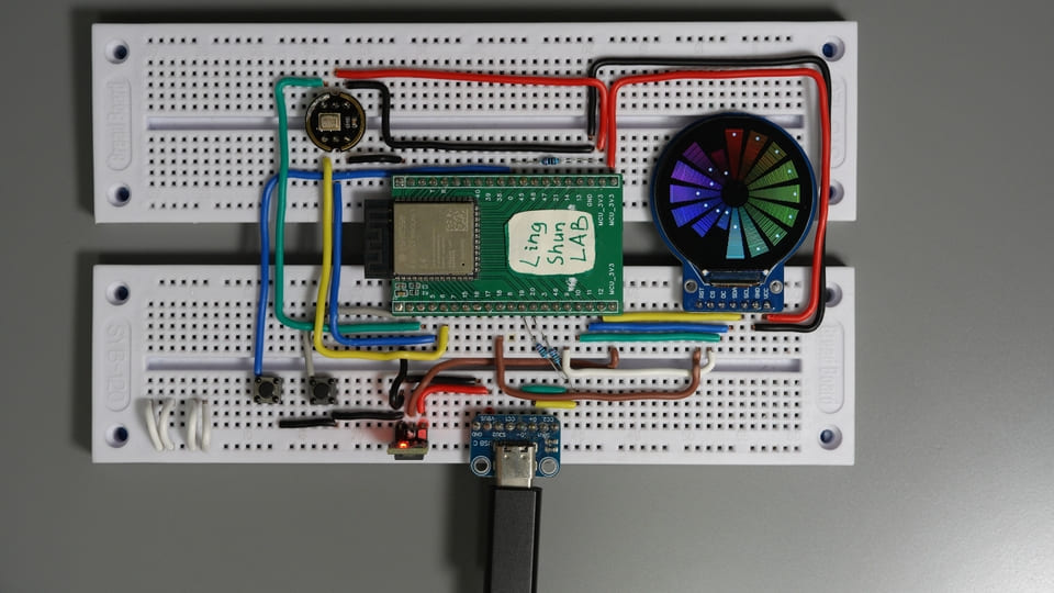
This article walks you through building a real-time, sound-responsive circular rainbow spectrum analyzer using ESP32-S3 + INMP441 digital microphone + GC9A01 circular TFT screen, from wiring to code. Any maker with a bit of experience should see results within 45 minutes.
Demo
- Real-time microphone audio capture (44.1kHz, 16-bit)
- 512-point FFT analysis, divided into 16 frequency bands
- Rainbow bars radiate outward on the circular screen, with white peak dots slowly descending
- Refresh rate around 20fps — perfectly smooth to the naked eye
Component Overview
GC9A01 Circular TFT Screen
If a regular rectangular screen is a “candy bar phone,” then the GC9A01 is a “smartwatch face” — a 1.28-inch circular LCD with the GC9A01 driver chip, using SPI, running at 3.3V. Just 8 wires and you’re up and running.
| Parameter | Value |
|---|---|
| Screen size | 1.28 inches |
| Resolution | 240 × 240 pixels |
| Interface | SPI (4-wire) |
| Operating voltage | 3.3V |
| Driver chip | GC9A01 |
| Panel type | IPS (full viewing angle) |
Why choose it: The most common small circular screen on the market, natively supported by the Arduino_GFX library, initialized in just 5 lines of code, and very few pitfalls.
INMP441 MEMS Digital Microphone
The INMP441 is an omnidirectional MEMS digital microphone — in plain terms: it outputs a digital I2S signal directly, no ADC needed. It’s like hiring a simultaneous interpreter that translates whatever you say into digital language the MCU can understand, bypassing all the hassle of analog signal processing.
| Parameter | Value |
|---|---|
| Interface | I2S (digital audio) |
| Operating voltage | 1.8V – 3.3V |
| Frequency response | 60Hz – 15kHz |
| Signal-to-noise ratio | 61dBA |
| Sensitivity | -26dBFS (typical) |
| Pick-up pattern | Omnidirectional |
Why choose it: Clean I2S interface, no extra ADC needed, and the 61dBA SNR is a significant step up from most cheap analog microphone capsules — more than sufficient for a spectrum analyzer.
It’s worth noting that the INMP441 was originally manufactured by InvenSense (later acquired by TDK), and has long been listed as Obsolete (discontinued) by the manufacturer. At mainstream component distributors like Mouser and DigiKey, it has been marked as end-of-life. However, on platforms like AliExpress and Taobao, plenty of cheap INMP441 blue/black modules are still readily available. This is mainly because the Chinese market still has large quantities of surplus stock, or some compatible/refurbished domestic chips continue to use this name. If you’re just doing personal DIY, writing tutorials, or running small demos, the modules currently available will still work fine.
Therefore, if you’re developing a commercial product, this module is not the recommended choice.
BOM
| Component | Model / Specification | Qty |
|---|---|---|
| MCU development board | ESP32-S3 (with USB-C) | 1 |
| Circular TFT screen | GC9A01, 1.28 inch, 240×240 | 1 |
| Digital microphone | INMP441 I2S module | 1 |
| Dupont wires | As needed |
Component Pin Descriptions
GC9A01 Screen Pins
| Pin | Function |
|---|---|
| VCC | Power positive (connect to 3.3V) |
| GND | Power ground |
| SCL / CLK | SPI clock |
| SDA / MOSI | SPI data (host transmit) |
| CS | Chip select (active low) |
| DC | Data / command select |
| RST | Reset (triggered by low level) |
| BL | Backlight control (connect to 3.3V for always-on, or to a GPIO for PWM dimming) |
INMP441 Microphone Pins
| Pin | Function |
|---|---|
| VDD | Power positive (connect to 3.3V) |
| GND | Power ground |
| SD | I2S data output (connect to ESP32 data input) |
| WS | Word clock / frame sync (left/right channel select) |
| SCK | Bit clock |
| L/R | Channel select: GND = left channel, 3.3V = right channel, must not be left floating |
Wiring
Tip: Double-check each wire against the table as you go — it saves 80% of debugging time.
GC9A01 Screen Wiring
| Module Pin | ESP32-S3 | Wire Color Reference |
|---|---|---|
| VCC | 3.3V | Red |
| GND | GND | Gray |
| SCL / CLK | GPIO12 | Yellow |
| SDA / MOSI | GPIO11 | Blue |
| CS | GPIO9 | Green |
| DC | GPIO10 | Orange |
| RST | GPIO18 | Purple |
| BL | GPIO7 / 3.3V | Cyan |
INMP441 Microphone Wiring
| Module Pin | ESP32-S3 | Wire Color Reference |
|---|---|---|
| VDD | 3.3V | Red |
| GND | GND | Gray |
| SD | GPIO4 | Blue |
| WS | GPIO5 | Green |
| SCK | GPIO6 | Yellow |
| L/R | GND (left channel) | Gray |
⚠️ The L/R pin must be connected — do not leave it floating. A floating L/R pin results in an undefined channel selection, and you’ll capture nothing but noise. The spectrum bars will jump randomly with no relation to actual sound — don’t ask me how I know.
- Always use 3.3V power supply — do not connect to 5V
- INMP441 L/R pin connected to GND = left channel output
- Wire everything up first, use a multimeter to verify power and ground connections before powering on, to avoid short circuits
Required Libraries
In Arduino IDE → Tools → Manage Libraries, search and install:
| Library | Author | Tested Version | Purpose |
|---|---|---|---|
Arduino_GFX_Library | moononournation | v1.6.5 | GC9A01 screen driver |
arduinoFFT | kosme | v2.0.4 | Fast Fourier Transform |
The I2S driver (
driver/i2s.h) is a built-in ESP32 library — no additional installation needed.Arduino IDE 2.3.x or later is recommended. The older 1.x versions have unstable ESP32-S3 support.
Complete Code
#include <Arduino_GFX_Library.h>
#include <driver/i2s.h>
#include <arduinoFFT.h>

// ====== Step 1: Define display pins ======
#define TFT_SCK   12
#define TFT_MOSI  11
#define TFT_CS    9
#define TFT_DC    10
#define TFT_RST   18
#define TFT_BL    7

// ====== Step 2: Define microphone pins ======
#define I2S_WS    5
#define I2S_SD    4
#define I2S_SCK   6
#define I2S_PORT  I2S_NUM_0

// ====== FFT parameters ======
#define SAMPLES   512
#define BANDS     16

// ====== Initialize GC9A01 display ======
Arduino_DataBus *bus = new Arduino_ESP32SPI(
  TFT_DC, TFT_CS, TFT_SCK, TFT_MOSI, -1);
Arduino_GFX *gfx = new Arduino_GC9A01(
  bus, TFT_RST, 0, true);

// ====== FFT buffers ======
double vReal[SAMPLES];
double vImag[SAMPLES];
ArduinoFFT<double> FFT = ArduinoFFT<double>(
  vReal, vImag, SAMPLES, 44100);

// ====== Band energy and peaks ======
float bandValues[BANDS];
float peakValues[BANDS];
int16_t sampleBuf[SAMPLES];

// ====== Color utility: HSL to RGB565 ======
uint16_t hslToRgb565(float h, float s, float l) {
  float c = (1.0f - fabsf(2.0f * l - 1.0f)) * s;
  float x = c * (1.0f - fabsf(fmodf(h / 60.0f, 2.0f) - 1.0f));
  float m = l - c / 2.0f;
  float r, g, b;
  if (h < 60)       { r=c; g=x; b=0; }
  else if (h < 120) { r=x; g=c; b=0; }
  else if (h < 180) { r=0; g=c; b=x; }
  else if (h < 240) { r=0; g=x; b=c; }
  else if (h < 300) { r=x; g=0; b=c; }
  else              { r=c; g=0; b=x; }
  uint8_t R = (uint8_t)((r + m) * 31);
  uint8_t G = (uint8_t)((g + m) * 63);
  uint8_t B = (uint8_t)((b + m) * 31);
  return (R << 11) | (G << 5) | B;
}

// ====== Step 3: Initialize microphone I2S ======
void setupMicrophone() {
  const i2s_config_t i2s_config = {
    .mode = (i2s_mode_t)(I2S_MODE_MASTER | I2S_MODE_RX),
    .sample_rate = 44100,
    .bits_per_sample = I2S_BITS_PER_SAMPLE_16BIT,
    .channel_format = I2S_CHANNEL_FMT_ONLY_LEFT,
    .communication_format = I2S_COMM_FORMAT_STAND_I2S,
    .intr_alloc_flags = ESP_INTR_FLAG_LEVEL1,
    .dma_buf_count = 8,
    .dma_buf_len = 64,
    .use_apll = false,
    .tx_desc_auto_clear = false,
    .fixed_mclk = 0
  };
  const i2s_pin_config_t pin_config = {
    .bck_io_num = I2S_SCK,
    .ws_io_num = I2S_WS,
    .data_out_num = -1,
    .data_in_num = I2S_SD
  };
  i2s_driver_install(I2S_PORT, &i2s_config, 0, NULL);
  i2s_set_pin(I2S_PORT, &pin_config);
  i2s_start(I2S_PORT);
}

void setup() {
  Serial.begin(115200);

  // Step 4: Turn on backlight, initialize display
  pinMode(TFT_BL, OUTPUT);
  digitalWrite(TFT_BL, HIGH);
  gfx->begin();
  gfx->fillScreen(0x0000);

  // Step 5: Initialize microphone
  setupMicrophone();

  memset(peakValues, 0, sizeof(peakValues));
}

// ====== Draw circular spectrum ======
void drawCircularSpectrum() {
  int cx = 120, cy = 120;
  int innerR = 25;
  int maxLen = 85;
  float angleStep = 2.0f * PI / BANDS;
  float barWidth = angleStep * 0.7f;

  gfx->fillScreen(0x0000);

  for (int i = 0; i < BANDS; i++) {
    float angle = i * angleStep - PI / 2.0f;
    float hue = (float)i / BANDS * 360.0f;
    float val = bandValues[i];
    int barLen = (int)(val * maxLen);

    for (int r = innerR; r < innerR + barLen; r += 2) {
      float t = (float)(r - innerR) / maxLen;
      uint16_t color = hslToRgb565(hue, 1.0f, 0.3f + t * 0.3f);
      float x1 = cx + cosf(angle - barWidth/2) * r;
      float y1 = cy + sinf(angle - barWidth/2) * r;
      float x2 = cx + cosf(angle + barWidth/2) * r;
      float y2 = cy + sinf(angle + barWidth/2) * r;
      gfx->drawLine(x1, y1, x2, y2, color);
    }

    if (peakValues[i] > 0.02f) {
      int peakR = innerR + (int)(peakValues[i] * maxLen) + 3;
      float px = cx + cosf(angle) * peakR;
      float py = cy + sinf(angle) * peakR;
      gfx->fillCircle(px, py, 2, 0xFFFF);
    }

    peakValues[i] *= 0.95f;
    if (bandValues[i] > peakValues[i]) {
      peakValues[i] = bandValues[i];
    }
  }
}

void loop() {
  // Step 6: Read microphone I2S data
  size_t bytes_read = 0;
  i2s_read(I2S_PORT, sampleBuf, sizeof(sampleBuf),
           &bytes_read, portMAX_DELAY);

  // Step 7: Fill FFT real part with sample data
  for (int i = 0; i < SAMPLES; i++) {
    vReal[i] = (double)sampleBuf[i];
    vImag[i] = 0.0;
  }

  // Step 8: Execute FFT
  FFT.windowing(FFT_WIN_TYP_HAMMING, FFT_FORWARD);
  FFT.compute(FFT_FORWARD);
  FFT.complexToMagnitude();

  // Step 9: Map FFT results to 16 bands
  memset(bandValues, 0, sizeof(bandValues));
  int specLen = SAMPLES / 2;
  for (int i = 0; i < BANDS; i++) {
    int start = (int)(pow((float)i / BANDS, 1.8f) * specLen * 0.7f);
    int end   = (int)(pow((float)(i+1) / BANDS, 1.8f) * specLen * 0.7f);
    if (end <= start) end = start + 1;
    float sum = 0;
    for (int j = start; j < end && j < specLen; j++) {
      sum += (float)vReal[j];
    }
    float avg = sum / (end - start);
    bandValues[i] = constrain(avg / 5000.0f, 0.0f, 1.0f);
  }

  // Step 10: Draw circular spectrum
  drawCircularSpectrum();
}
Code Walkthrough
① Why SAMPLES = 512? 512 is a power of two, which is where the FFT algorithm is most efficient. At a 44.1kHz sample rate, a 512-point FFT gives a frequency resolution of about 86Hz — good enough for our purposes. Dropping to 256 is faster but loses frequency detail, while going up to 1024 is finer but noticeably reduces the frame rate.
② Why use pow(…, 1.8) for band distribution? Linear frequency band allocation would cram most data into the high-frequency region while leaving the low end empty. Exponential distribution gives the low-frequency bands narrower ranges (more detail) and the high-frequency bands wider ranges (consolidating noise), which better matches how human hearing perceives frequency — and the result looks more “natural.”
③ Where does the normalization divisor of 5000 come from? This value depends on your microphone’s distance from the sound source and the ambient volume — different scenarios require manual tuning. If the bars are always maxed out (energy being clipped), increase the 5000; if the bars are too short to see, decrease it.
*④ What does peakValues[i] = 0.95 do? This is the classic “peak hold + slow decay” technique: when the sound suddenly stops, the white peak dot doesn’t vanish instantly — instead it’s multiplied by 0.95 each frame for a gradual descent. Visually it’s much smoother, similar to the effect on professional audio equipment.
Troubleshooting
Don’t panic — 90% of issues come from these common causes:
Screen is completely black, nothing displays First check whether the backlight (BL pin) is actually pulled high (if your module doesn’t have a BL pin, ignore this). Then check if the four SPI wires (SCK / MOSI / CS / DC) are wired correctly or have loose connections. Use a multimeter to verify VCC is getting 3.3V. If the backlight is on but the screen is still black, nine times out of ten CS or DC is wired wrong — try swapping them.
Spectrum bars don’t move at all, or jump randomly with no relation to sound First thing: confirm the INMP441 L/R pin is connected to GND — this is the most common pitfall. A floating L/R pin causes undefined channel selection, and you’ll capture nothing but random noise. After confirming L/R is correct, check the GPIO pin numbers for the SD / WS / SCK wires.
All spectrum bars are maxed out (energy always at maximum)
Increase the value 5000 in bandValues[i] = constrain(avg / 5000.0f, ...) to something like 15000 or 30000. Having the microphone too close to the sound source can also cause this — try moving it about 30cm away first.
Spectrum bars respond, but only a few move The sound source you’re testing with might have a narrow frequency range (e.g., a single-tone whistle). Try playing full-spectrum music (with bass, vocals, and high-frequency instruments) and see if all frequency bands respond.
Compilation fails: ArduinoFFT template class errors
Make sure you have arduinoFFT (kosme’s version) v2.x installed. The v1.x syntax is ArduinoFFT FFT (no template parameters), while v2.x uses ArduinoFFT<double> — the two versions have incompatible APIs. Just update to the latest version in the Library Manager.
FAQ
Q: What happens if the INMP441 L/R pin is left unconnected? A: The channel selection is left floating, and the microphone output behavior becomes undefined. In practice, you’ll almost certainly capture nothing but random noise data, and the spectrum bars will jump randomly with no relation to sound. GND = left channel, 3.3V = right channel — pick one, it cannot be left unconnected.
Q: Can I change SAMPLES to 1024? What’s the impact? A: Yes. Frequency resolution improves from ~86Hz to ~43Hz, giving richer low-frequency detail. The trade-off is that each frame’s capture and computation time doubles, dropping the refresh rate from ~20fps to ~10fps. For a spectrum visualizer, 10fps is still visually acceptable.
Q: Will INMP441 work properly with only 3.3V? A: Absolutely. The INMP441 supports 1.8V to 3.3V power supply. 3.3V is the most common operating voltage — no additional voltage regulator needed.
Q: Is the CPU load on the ESP32-S3 high? Will it affect other tasks? A: A 512-point FFT on the ESP32-S3 at 240MHz takes roughly 10%–15% of a single core’s CPU time. If you also need to run Wi-Fi or Bluetooth, consider putting FFT + rendering on Core 0 and network tasks on Core 1 — they won’t interfere with each other.
Q: Can I replace the GC9A01 with an ST7789 or other screen driver?
A: Yes. Arduino_GFX_Library supports dozens of driver chips. Just replace Arduino_GC9A01 in the code with the corresponding class (e.g., Arduino_ST7789), update the resolution parameters, and follow the new screen’s datasheet for wiring. Note that non-circular screens will require recalculating the center coordinates.
Q: There’s “floor noise” when it’s quiet — the bars don’t go to zero. What should I do?
A: The INMP441 has inherent noise floor (SNR of 61dBA means there’s always a small amount of ambient noise being captured). You can add a noise gate: before the mapping, add a line like if (avg < 200) avg = 0; — this will make the bars go completely to zero when it’s quiet. Increasing the normalization divisor also helps.
Q: Which version of the I2S driver does the ESP32-S3 use?
A: This article uses the legacy ESP-IDF v4.x style I2S driver (i2s_driver_install / i2s_read). ESP-IDF v5.x introduced a new I2S API (i2s_new_channel, etc.). If your ESP32-S3 board support package has been upgraded to 3.x, you’ll need to rewrite the setupMicrophone() function to use the new API.
Extending the Project
- Upgrade to 32 frequency bands with a larger circular screen (e.g., 2.1-inch GC9A01A) for finer spectrum detail
- Add touch buttons to switch display modes (circular radiation / vertical bars / oscilloscope waveform)
- Connect to Wi-Fi and push spectrum data to a browser for web-based rendering
- Use two INMP441 modules for stereo, displaying left and right channels in different colors