ESP32-S3 Digital Spirit Level with GC9A01 Round Display and MPU6050 IMU (SPI + I2C + Arduino)
Difficulty: ⭐⭐☆☆☆ (Beginner-friendly) Estimated time: 45 minutes Tested with: Arduino IDE 2.3.8 | Arduino_GFX_Library v1.6.5 | MPU6050_light v1.2.1
One-sentence summary: ESP32-S3 drives a GC9A01 round TFT + MPU6050 6-axis IMU to create a real-time bubble spirit level where the bubble color shifts with tilt angle (green -> yellow -> red), complete with wiring tables and Arduino code.
TL;DR (Quick Start):
- MPU6050 wiring: SDA -> GPIO 15, SCL -> GPIO 16, AD0 -> GND (fixed I2C address 0x68)
- GC9A01 wiring: CLK -> GPIO 12, MOSI -> GPIO 11, CS -> GPIO 9, DC -> GPIO 10, RST -> GPIO 18, BL -> GPIO 7
- Install libraries:
GFX Library for Arduino(by moononournation) +MPU6050_light(by rfetick)- Flash the code, power on, keep the device flat and still for about 1 second until the calibration message disappears, then tilt away and watch the bubble move
Introduction
Have you ever tried installing a shelf by eye, thinking “that looks pretty level,” only to put something on it and watch everything slide to one side?
That’s exactly the kind of person I am. I couldn’t find a traditional spirit level, so I dug through my parts bin on a whim — and there sat a GC9A01 round display and an MPU6050, both gathering dust. Put them together and you’ve got everything you need for a digital spirit level.
Even better, the round screen is a perfect visual match for a bubble level: bubble centered = green, slightly off = yellow, tilted too far = red. You can read it at a glance — no manual required.
This article’s goal: start from scratch — wiring -> install libraries -> flash code -> watch the bubble move. Follow along and you’ll have a working replica.
Demo
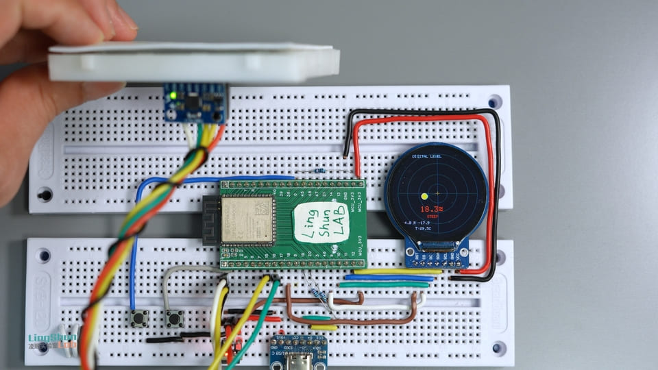
The screen displays four items in real time:
- Center bubble: moves with device tilt, with three color zones (green = level / yellow = slight tilt / red = significant tilt)
- Combined tilt angle (°): the composite of Pitch and Roll, shown in large text
- Pitch / Roll individual values: separate readings for pitch angle and roll angle
- Chip temperature: reading from the MPU6050’s built-in temperature sensor (typically higher than room temperature — explained later)
Component Overview
GC9A01 Round TFT Display
Think of it as a phone screen cut into a perfect circle — 240x240 resolution isn’t cutting-edge, but sitting behind round glass on your desk, it makes an ideal spirit level dial.
| Parameter | Value |
|---|---|
| Resolution | 240 x 240 px (circular display area) |
| Interface | SPI (up to 80 MHz) |
| Supply voltage | 3.3V |
| Color depth | 65K colors (RGB565) |
| Panel type | IPS |
Why this display: the round dial is a natural fit for a bubble level, and the high-speed SPI interface easily handles 20fps animation.
MPU6050 6-Axis IMU
Think of it as the gyroscope and accelerometer in your phone combined into one chip — it’s the same type of sensor responsible for auto-rotating your screen and counting your steps. The MPU6050 packs a 3-axis accelerometer (detects tilt direction) and a 3-axis gyroscope (detects rotation rate) into a single 4mm x 4mm package, and throws in a temperature sensor for good measure.
| Parameter | Value |
|---|---|
| Accelerometer range | ±2 / ±4 / ±8 / ±16 g (configurable) |
| Gyroscope range | ±250 / ±500 / ±1000 / ±2000 °/s (configurable) |
| ADC resolution | 16-bit |
| Interface | I2C (up to 400 kHz fast mode) |
| Supply voltage | 3.3V (VDD range: 2.375 ~ 3.46V) |
| I2C address | 0x68 (AD0 = GND) / 0x69 (AD0 = VCC) |
Why this sensor: extremely affordable, excellent library support, and MPU6050_light outputs fused angles directly — no need to write your own Kalman filter.
Bill of Materials (BOM)
| Component | Model / Spec | Qty |
|---|---|---|
| MCU development board | ESP32-S3 | 1 |
| Round TFT display | GC9A01 240x240 IPS | 1 |
| 6-axis IMU sensor | MPU6050 module | 1 |
| Jumper wires | Dupont wires | A few |
Pin Reference
GC9A01 Pins
| Pin label | Function |
|---|---|
| VCC | 3.3V main power |
| GND | Ground |
| SCL / CLK | SPI clock (SCLK) |
| SDA / MOSI | SPI MOSI data |
| CS | Chip select (active low) |
| DC | Data / command select |
| RST | Hardware reset (active low) |
| BL | Backlight control |
MPU6050 Pins
| Pin label | Function |
|---|---|
| VCC | 3.3V main power |
| GND | Ground |
| SDA | I2C data line |
| SCL | I2C clock line |
| INT | Interrupt output (not connected in polling mode) |
| AD0 | I2C address select (connect to GND = 0x68) |
| XDA / XCL | Auxiliary I2C interface (not used in this project) |
Wiring
Tip: wire one row at a time using the table below, and check off each connection as you go. This simple habit eliminates 80% of troubleshooting headaches.
MPU6050 -> ESP32-S3
| MPU6050 Pin | ESP32-S3 Pin | Notes |
|---|---|---|
| VCC | 3.3V | Main power |
| GND | GND | Common ground |
| SDA | GPIO 15 | I2C data line |
| SCL | GPIO 16 | I2C clock line |
| AD0 | GND | Fixes I2C address to 0x68 |
| INT / XDA / XCL | Not connected | Not needed for this project |
About I2C pull-up resistors: the standard practice is to connect a 4.7kΩ pull-up resistor from each of SDA and SCL to 3.3V, which significantly improves noise immunity during high-speed reads. This example omits them, but if you’re building a finished product, it’s recommended to add them.
GC9A01 -> ESP32-S3
| GC9A01 Pin | ESP32-S3 Pin | Notes |
|---|---|---|
| VCC | 3.3V | Main power |
| GND | GND | Common ground |
| SCL / CLK | GPIO 12 | SPI clock |
| SDA / MOSI | GPIO 11 | SPI data |
| CS | GPIO 9 | Chip select |
| DC | GPIO 10 | Data / command select |
| RST | GPIO 18 | Hardware reset |
| BL | GPIO 7 | Backlight (optional — some modules lack this pin. Controlled via HIGH/LOW in code, or connect directly to 3.3V for always-on) |
Required Libraries
In the Arduino IDE, go to Tools -> Manage Libraries… and search for:
| Library name | Author | Tested version |
|---|---|---|
| GFX Library for Arduino | moononournation | v1.6.5 |
| MPU6050_light | rfetick | v1.2.1 |
Different versions may have API changes, so it’s best to install the versions listed above. After installing, restart Arduino IDE before opening the project.
Full Code
/**
 * ESP32-S3 + GC9A01 + MPU6050 Digital Spirit Level
 * Digital Spirit Level
 *
 * Wiring:
 *   GC9A01  -> SCL=12, SDA=11, CS=9, DC=10, RST=18, BL=7
 *   MPU6050 -> SDA=15, SCL=16, AD0=GND (I2C address 0x68)
 */

#include <Arduino_GFX_Library.h>
#include <Wire.h>
#include <MPU6050_light.h>

// ---- Color definitions (RGB565 format) ----
#define COLOR_BG       0x0863   // Dark background
#define COLOR_GRID     0x1A69   // Grid lines
#define COLOR_GREEN    0x07E6   // Bubble centered -> green
#define COLOR_YELLOW   0xFEA0   // Slight tilt -> yellow
#define COLOR_RED      0xF820   // Excessive tilt -> red
#define COLOR_TEXT     0xC618   // Normal text
#define COLOR_ACCENT   0xFD20   // Center crosshair

// ---- GC9A01 SPI pins ----
#define TFT_SCK  12
#define TFT_SDA  11
#define TFT_CS    9
#define TFT_DC   10
#define TFT_RST  18
#define TFT_BL    7

// ---- MPU6050 I2C pins (must match wiring table) ----
#define MPU_SDA  15   // SDA -> GPIO 15
#define MPU_SCL  16   // SCL -> GPIO 16

// ---- Initialize display driver ----
// Step 1: Create SPI bus, parameter order: DC, CS, SCK, MOSI, MISO
Arduino_DataBus *bus = new Arduino_ESP32SPI(
    TFT_DC, TFT_CS, TFT_SCK, TFT_SDA,
    GFX_NOT_DEFINED
);
// Step 2: Create GC9A01 screen object (rotation=0, IPS panel=true)
Arduino_GFX *gfx = new Arduino_GC9A01(
    bus, TFT_RST, 0, true
);
// Step 3: Create 240x240 off-screen canvas (double buffer, prevents tearing)
Arduino_Canvas *canvas = new Arduino_Canvas(
    240, 240, gfx
);

// ---- MPU6050 ----
MPU6050 mpu(Wire);

// ---- Frame rate control ----
const int16_t cx = 120, cy = 120;    // Screen center coordinates (pixels)
unsigned long lastFrame = 0;
const int frameDelay = 1000 / 20;    // Target frame rate: 20fps -> 50ms per frame

// ---- Function forward declarations ----
void drawGrid();
void drawBubble(float pitch, float roll);
void drawReadouts(float pitch, float roll, float temp);

// =============================================================
void setup() {
    Serial.begin(115200);
    delay(500);
    Serial.println("=== ESP32-S3 Digital Spirit Level Starting ===");

    // Step 1: Initialize display and backlight
    gfx->begin();
    pinMode(TFT_BL, OUTPUT);
    digitalWrite(TFT_BL, HIGH);    // Turn on backlight
    canvas->begin();
    Serial.println("[OK] Display initialized");

    // Step 2: Initialize I2C and scan the bus (useful for debugging wiring)
    Wire.begin(MPU_SDA, MPU_SCL);
    Serial.print("[DBG] Scanning I2C bus SDA=");
    Serial.print(MPU_SDA);
    Serial.print(" SCL=");
    Serial.println(MPU_SCL);

    byte found = 0;
    for (byte addr = 1; addr < 127; addr++) {
        Wire.beginTransmission(addr);
        if (Wire.endTransmission() == 0) {
            Serial.print("  Found I2C device at 0x");
            Serial.println(addr, HEX);
            found++;
        }
    }
    if (found == 0) {
        Serial.println("[ERROR] No I2C devices found! Check wiring.");
    }

    // Step 3: Initialize MPU6050
    byte status = mpu.begin();
    if (status == 0) {
        Serial.println("[OK] MPU6050 connected");
    } else {
        Serial.println("[ERROR] MPU6050 not responding! Check wiring or I2C address.");
    }

    // Step 4: Auto-calibrate gyroscope (keep device flat and still for ~1 second)
    Serial.println("[DBG] Calibrating, keep device flat and still...");
    canvas->fillScreen(COLOR_BG);
    canvas->setTextColor(COLOR_TEXT);
    canvas->setTextSize(1);
    canvas->setCursor(60, 110);
    canvas->print("Calibrating...");
    canvas->setCursor(55, 125);
    canvas->print("Keep device flat");
    canvas->flush();

    delay(1000);
    mpu.calcOffsets();    // Auto-calculate accelerometer and gyroscope zero offsets

    Serial.print("[DBG] Accel offsets: ");
    Serial.print(mpu.getAccXoffset());  Serial.print(", ");
    Serial.print(mpu.getAccYoffset());  Serial.print(", ");
    Serial.println(mpu.getAccZoffset());
    Serial.print("[DBG] Gyro offsets: ");
    Serial.print(mpu.getGyroXoffset()); Serial.print(", ");
    Serial.print(mpu.getGyroYoffset()); Serial.print(", ");
    Serial.println(mpu.getGyroZoffset());
    Serial.println("[OK] Calibration complete, running!");
}

// =============================================================
static int logCnt = 0;    // Debug log throttle counter

void loop() {
    unsigned long now = millis();
    if (now - lastFrame < frameDelay) return;    // Frame rate throttle
    lastFrame = now;

    // Step 1: Read sensor
    mpu.update();
    float pitch = mpu.getAngleY();     // Pitch angle (forward/backward tilt)
    float roll  = -mpu.getAngleX();    // Roll angle (left/right tilt, negated to match visual direction)
    float temp  = mpu.getTemp();       // Chip temperature (typically higher than ambient)

    // Debug log: print every 20 frames (~1 second), does not affect frame rate
    if (++logCnt >= 20) {
        logCnt = 0;
        Serial.print("[DBG] pitch="); Serial.print(pitch, 2);
        Serial.print(" roll=");       Serial.print(roll,  2);
        Serial.print(" temp=");       Serial.print(temp,  1);
        Serial.print(" | accX=");     Serial.print(mpu.getAccX(), 2);
        Serial.print(" accY=");       Serial.print(mpu.getAccY(), 2);
        Serial.print(" accZ=");       Serial.println(mpu.getAccZ(), 2);
    }

    // Step 2: Clamp — at ±45° the bubble stays at the edge, never leaves the circle
    pitch = constrain(pitch, -45.0f, 45.0f);
    roll  = constrain(roll,  -45.0f, 45.0f);

    // Step 3: Draw current frame
    canvas->fillScreen(COLOR_BG);        // Clear canvas
    drawGrid();                          // Grid lines
    drawBubble(pitch, roll);             // Bubble
    drawReadouts(pitch, roll, temp);     // Numeric readouts
    canvas->flush();                     // Push to screen
}

// =============================================================
// Draw background grid circles and center crosshair
void drawGrid() {
    canvas->drawCircle(cx, cy,  25, COLOR_GRID);
    canvas->drawCircle(cx, cy,  50, COLOR_GRID);
    canvas->drawCircle(cx, cy,  80, COLOR_GRID);
    canvas->drawCircle(cx, cy, 105, COLOR_GRID);
    canvas->drawFastHLine(15, cy,  210, COLOR_GRID);
    canvas->drawFastVLine(cx, 15,  210, COLOR_GRID);
    // Center crosshair (accent color, more visible than grid)
    canvas->drawFastHLine(cx - 5, cy,     10, COLOR_ACCENT);
    canvas->drawFastVLine(cx,     cy - 5, 10, COLOR_ACCENT);
}

// Map bubble position from pitch/roll angles and color by distance
void drawBubble(float pitch, float roll) {
    // Map ±45° linearly to ±90px offset
    int16_t bx = cx + (int16_t)(roll  / 45.0f * 90.0f);
    int16_t by = cy + (int16_t)(pitch / 45.0f * 90.0f);

    // Calculate pixel distance from center to determine color tier
    float dist = sqrt((float)((bx - cx) * (bx - cx) + (by - cy) * (by - cy)));
    uint16_t color;
    if      (dist < 10) color = COLOR_GREEN;    // Within ~±5°: level
    else if (dist < 40) color = COLOR_YELLOW;   // Within ~±20°: slight tilt
    else                color = COLOR_RED;       // Beyond ±20°: significant tilt

    // Line from center to bubble + filled bubble + white outline
    canvas->drawLine(cx, cy, bx, by, COLOR_GRID);
    canvas->fillCircle(bx, by, 8, color);
    canvas->drawCircle(bx, by, 8, 0xFFFF);
}

// Draw angle values, status text, and temperature
void drawReadouts(float pitch, float roll, float temp) {
    float total = sqrt(pitch * pitch + roll * roll);    // Combined tilt angle

    canvas->setTextSize(1);
    canvas->setTextColor(COLOR_TEXT);

    // Top title
    canvas->setCursor(55, 18);
    canvas->print("DIGITAL LEVEL");

    // Combined angle: large font, color synced with bubble
    canvas->setTextSize(2);
    uint16_t color;
    if      (total < 1)  color = COLOR_GREEN;
    else if (total < 10) color = COLOR_YELLOW;
    else                 color = COLOR_RED;
    canvas->setTextColor(color);
    canvas->setCursor(75, 155);
    canvas->print(total, 1);
    canvas->print((char)247);    // Degree symbol (ASCII 247)

    // Status text
    canvas->setTextSize(1);
    canvas->setCursor(80, 178);
    if      (total < 1)  canvas->print("  LEVEL");
    else if (total < 10) canvas->print(" TILTED");
    else                 canvas->print("  STEEP");

    // Pitch / Roll individual readings
    canvas->setTextColor(COLOR_TEXT);
    canvas->setCursor(20, 195);
    canvas->print("P:"); canvas->print(pitch, 1);
    canvas->print(" R:"); canvas->print(roll,  1);

    // Temperature (junction temperature, typically higher than room temperature)
    canvas->setCursor(60, 210);
    canvas->print("T:"); canvas->print(temp, 1);
    canvas->print("C");
}
Code Walkthrough
Initialization (setup)
The setup runs through four steps in order: display init -> I2C scan -> MPU6050 init -> gyroscope calibration. The orientation of your module at this moment becomes the calibrated center point.
The display uses Arduino_Canvas for off-screen double buffering — all drawing happens in memory first, then a single flush() pushes everything to the screen. This prevents tearing or partial frames.
The I2C scan section prints discovered device addresses to the serial monitor. On first power-up, open the serial monitor to confirm the MPU6050 is detected (you should see Found I2C device at 0x68).
mpu.calcOffsets() performs automatic calibration over approximately 1 second. During this time, keep the device flat and still. Calibration runs on every boot, so always place the device flat first and wait for the on-screen message to disappear before using it.
Main loop (loop)
The frame rate is locked at 20fps. Each frame does four things: read sensor -> clamp values -> draw -> push to screen.
The roll = -mpu.getAngleX() line has a negative sign — this ensures the bubble moves in the same direction as the physical tilt. Without the negation, the bubble would move in the opposite direction. If your mounting orientation differs, you can adjust the sign to suit.
Bubble color uses three tiers: less than 10px from center = green, less than 40px = yellow, otherwise = red. This roughly corresponds to within ±5°, within ±20°, and beyond ±20°.
Troubleshooting
Don’t panic — 90% of issues come down to wiring and address configuration:
Screen is all white / all black, no display at all
First confirm VCC is connected to 3.3V, not 5V (GC9A01 is not 5V tolerant). Check that the BL backlight pin is connected. Then verify CS, DC, and RST are on the correct pins — a wrong CS means the screen won’t respond, and a floating RST keeps it stuck in reset. You can test by connecting BL directly to 3.3V for always-on backlight. If the screen lights up white, the display itself is fine and the issue is SPI initialization.
Serial monitor shows [ERROR] No I2C devices found
Use a multimeter to check whether the MPU6050’s VCC pin has 3.3V. Confirm SDA and SCL aren’t swapped (SDA -> GPIO 15, SCL -> GPIO 16). AD0 must be explicitly connected to GND — if left floating, some modules have unstable addressing and the I2C bus won’t respond.
Bubble jitters constantly, won’t stabilize
The device wasn’t completely still during power-on calibration. Power cycle, place it on a flat surface, and wait for the calibration message to disappear before using. If the surface itself is vibrating (nearby printer, fan, etc.), move to a different spot.
Pitch or Roll direction is inverted
Depending on your board’s mounting orientation, adjust the sign in front of the corresponding angle in the code: change pitch = mpu.getAngleY() to pitch = -mpu.getAngleY(), or adjust the roll line, until the direction is correct.
Temperature reads 10-20 degrees above room temperature
This is normal. The MPU6050 measures junction temperature, which is typically 10~20°C higher than ambient. It’s for reference only. If you need accurate ambient temperature, use a dedicated sensor like the DS18B20.
Screen flickers or shows visible tearing
The code uses Arduino_Canvas double buffering, so tearing shouldn’t happen under normal conditions. If it persists, check that your SPI Dupont wires are secure, keep wires under 20cm, and consider adding a 100nF decoupling capacitor near the power pins.
FAQ
Q: What is the MPU6050’s angle update rate?
A: MPU6050_light reads over I2C at 400kHz fast mode, with raw data sampling up to 1kHz. This code limits the frame rate to 20fps (20Hz refresh). If you need a higher refresh rate, reduce frameDelay — in practice, anything up to about 40fps is stable (limited by SPI display push speed).
Q: Can I use different GPIO pins?
A: Yes, just modify the #define macros at the top of the code. For the GC9A01 SPI pins, ESP32-S3 hardware SPI (GPIO 11/12 are SPI2) gives the best performance. MPU6050 I2C pins can be any GPIO — just keep the code and wiring consistent.
Q: Can I replace the GC9A01 with a square display?
A: Yes. Replace Arduino_GC9A01 with the appropriate driver class (e.g., Arduino_ST7789 for ST7789), and update the Arduino_Canvas width, height, and center coordinates cx/cy. The drawing logic stays the same.
Q: Can the ESP32-S3’s 3.3V pin power both the GC9A01 and MPU6050 simultaneously?
A: Yes. The GC9A01 backlight draws about 20mA, and the MPU6050 typically consumes 3.5mW (1mA). The combined draw is well below the typical 300500mA limit of a development board’s 3.3V pin.
Q: Can I connect two MPU6050s on the same I2C bus?
A: Yes. Connect one AD0 to GND (address 0x68) and the other AD0 to VCC (address 0x69), sharing the same SDA/SCL lines. In your code, declare two MPU6050 objects and initialize each with its respective address.
Q: Do I need to recalibrate every time I power on?
A: Yes, this code calls mpu.calcOffsets() in setup() on every boot for dynamic calibration. If your project is permanently mounted, you can save the offsets to EEPROM and load them on startup, skipping the calibration wait.
Ideas for Extensions
- Add a button to switch display modes (spirit level / real-time angle graph / thermometer)
- Save calibration offsets to EEPROM to compensate for a fixed mounting surface angle
- Connect a passive buzzer that beeps when level
- Design a round dial skin to turn it into a magnetic compass or G-force display