DHT11 + GC9A01 Round Display: Build a Game Boy-Style Pixel Retro Thermohygrometer (Full Tutorial) (ESP32-S3 · SPI Wiring · Arduino Code)
TL;DR · Three-Minute Overview
No time for the long version? The core steps are right here. If you already know your way around, just fly through these:
- Wiring: DHT11 data pin → GPIO 47; GC9A01 round display SPI wiring: SCK→GPIO12, MOSI→GPIO11, CS→GPIO9, DC→GPIO10, RST→GPIO18, BL→GPIO7
- Install two libraries: In Arduino IDE, search for and install
Arduino_GFX_Library(Moon On Our Nation) andDHT sensor library(Adafruit)- Paste the full code from the bottom of this article, then in Arduino IDE select the board
ESP32S3 Dev Module- Compile and upload, wait about 30 seconds for the flash to finish
- Power up and verify: The round display lights up with a creamy-green background, the top half shows temperature (°C), the bottom half shows humidity (%), and extreme values automatically trigger a flashing alert ✅
Preface: A Thermohygrometer With Personality
Honestly, I’ve tried plenty of temperature-and-humidity display solutions—big OLED screens, little seven-segment LED modules, even just dumping numbers to the serial monitor… and every time I saw those lonely digits sitting on the screen, there was this indescribable emptiness to it. It worked fine, sure, but it was missing a bit of soul.
Then one day I dug out my old Game Boy, and that classic creamy yellow-green screen suddenly gave me an idea: since we’re showing numbers anyway, why not make it retro and fun?
And so this project was born—using an ESP32-S3 to drive a GC9A01 round LCD, paired with a DHT11 temperature-and-humidity sensor, hand-writing a pixel font from scratch, and porting the Game Boy DMG’s iconic four-tone green palette onto the round display to make a pixel-retro thermohygrometer that, sitting on your desk, makes people want to take a second look.
No off-the-shelf UI library, no heavy framework—just fillRect() building pixel digits one cell at a time. This kind of clunky, brute-force approach turns out to feel the most authentic.
Goal of this article: Even with zero experience, you can follow the whole flow end to end and end up seeing real-time temperature and humidity on the GC9A01 round display, with results slick enough to show off.
Demo
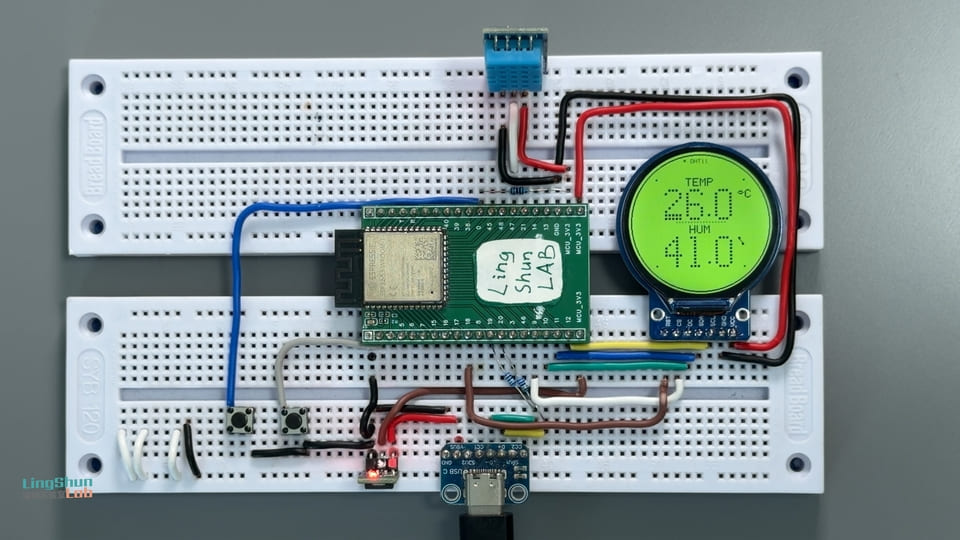
The final result in one sentence: 240x240 round display, creamy-green background, large pixel temperature and humidity values shown centered, smooth easing transitions when values change, automatic flashing alert when limits are exceeded, around 30fps, with zero tearing or flicker.
Component Overview
Before buying parts, let’s get acquainted with today’s three main characters.
ESP32-S3 · The Only Brain in This Project
The ESP32-S3 is Espressif’s Wi-Fi + Bluetooth dual-mode chip, but today we’re not using its networking chops—we’re using its plentiful GPIO, generous memory, and a plenty-fast SPI bus.
Analogy: If the GC9A01 round display is a TV set, the ESP32-S3 is the set-top box that pumps program signals into it—all the “content” originates from it, and the screen just handles “playback.”
Key specs:
- Clock speed 240 MHz (dual-core Xtensa LX7)
- Memory 512 KB SRAM, with optional PSRAM
- Hardware SPI support, can run up to 80 MHz
- 3.3V operating voltage, GPIO tolerates 3.3V (⚠️ never connect 5V signals)
GC9A01 Round Display · The Source of That Pixel-Retro Feel
The GC9A01 is a circular IPS LCD driver chip with a 240x240 resolution, usually sold as a small ~1.28-inch round display module with a standard 4-wire SPI interface.
Analogy: You know those old mechanical watch faces? The GC9A01 basically swaps that dial for a tiny programmable color screen that can show anything you want—it’s round, and that’s the elegance of it.
Key specs:
- Resolution: 240 x 240 pixels, circular viewing area
- Interface: 4-wire SPI (supports up to 80 MHz clock)
- Color depth: 16-bit RGB565 (65536 colors)
- Operating voltage: 3.3V (VCC and logic levels are both 3.3V, do NOT connect 5V!)
- Backlight: dedicated control pin (BL), high to turn on
DHT11 · The Nosy Little Neighbor
The DHT11 is a low-cost digital sensor that combines temperature and humidity in one package—just one data line brings back both readings, which is delightfully convenient.
Analogy: The DHT11 is like a nosy little neighbor who lives in your room and constantly reports back “how many degrees right now, how much water’s in the air.” The accuracy is just okay, but it’s good enough—and it’s quiet.
Key specs:
- Temperature range: 0 ~ 50°C, accuracy ±2°C
- Humidity range: 20% ~ 90% RH, accuracy ±5% RH
- Sampling interval: minimum 1 second (in code we read once every 2 seconds)
- Data interface: single-wire digital protocol (a 1-Wire variant)
- Operating voltage: 3.3V or 5V both work (we use 3.3V in this project)
BOM (Bill of Materials)
| Component | Model / Spec | Qty | Notes |
|---|---|---|---|
| Main dev board | ESP32-S3 Dev Module | 1 | Confirm it has an onboard USB-C flashing port |
| Round color display | GC9A01 · 1.28 in · 240×240 SPI | 1 | Pick a version with a BL pin when buying |
| Temperature & humidity sensor | DHT11 module (module version with pull-up resistor) | 1 | The module version is recommended—saves you wiring an external resistor |
| Jumper wires | Dupont wires (male-to-male / male-to-female) | a few | Have some of both kinds on hand |
Wiring
DHT11 → ESP32-S3
| DHT11 Pin | ESP32-S3 Pin | Notes |
|---|---|---|
| GND | GND | Common ground |
| VCC | 3V3 | Sensor power (3.3V) |
| DAT (DATA) | GPIO 47 | Data bus |
GC9A01 Round Display → ESP32-S3
| GC9A01 Pin | ESP32-S3 Pin | Notes |
|---|---|---|
| VCC | 3.3V | Main display power (⚠️ must be 3.3V, NOT 5V) |
| GND | GND | Common ground |
| SCL / CLK | GPIO 12 | SPI clock line |
| SDA / MOSI | GPIO 11 | SPI data line |
| CS | GPIO 9 | Chip select (active low) |
| DC | GPIO 10 | Data/command switch |
| RST | GPIO 18 | Hardware reset |
| BL | GPIO 7 | Backlight control (this pin may not exist on your board; the code pulls it high so it stays on; you can also wire it directly to 3.3V) |
💡 Practical reminder: After wiring, don’t power up in a rush—go through the table above line by line and double-check. In particular, confirm VCC is connected to 3.3V, not 5V (feeding a GC9A01 5V will basically kill it), and that the DHT11’s DAT is on the correct GPIO. Anyone who’s fallen into this pit knows the despair of “power on, and the screen never lights up again.”
Installing the Required Libraries
Open Arduino IDE, go to Tools → Manage Libraries, and search for and install the following two libraries:
1. Arduino_GFX_Library
- Search keyword:
Arduino_GFX - Author:
Moon On Our Nation - Purpose: Drives the GC9A01 round display, includes a double-buffered Canvas feature (the key to eliminating screen flicker)
2. DHT sensor library
- Search keyword:
DHT sensor library - Author:
Adafruit - When prompted “Install dependencies?”, choose Install all (this also pulls in Adafruit Unified Sensor)
After installation, it’s a good idea to restart Arduino IDE to make sure the library files load correctly.
Full Code
Code structure overview:
- Initialization phase: light the backlight → initialize the display → read the first DHT11 sample
- Main loop: read the sensor every 2 seconds, render a frame every 33ms (~30fps)
- Rendering mechanism: draw to an in-memory Canvas first, then flush to the screen all at once—eliminates tearing and flicker
- Pixel font: 5x7 for label text, 5x9 for large values, all hand-drawn cell-by-cell with
fillRect() - Alert animation: when temperature exceeds 35°C or drops below 5°C, or humidity exceeds 85% or drops below 20%, the digits flash at a 400ms interval
/**
 * ╔══════════════════════════════════════════════════╗
 * ║   ESP32-S3 Round Thermohygrometer · GAME BOY     ║
 * ║   Pixel Retro Edition                             ║
 * ║   Hardware: ESP32-S3 + GC9A01(240x240) + DHT11    ║
 * ║   Libraries: Arduino_GFX_Library + DHT (Adafruit) ║
 * ╚══════════════════════════════════════════════════╝
 *
 * Color scheme — Game Boy DMG classic four-tone green:
 *   PAL_BG      #CADC9F  Creamy yellow-green (background, source of the retro feel)
 *   PAL_LITE    #9BBC0F  Brightest green   (highlight accents)
 *   PAL_MID     #8BAC0F  Light green       (decorative dots)
 *   PAL_DARK    #306230  Medium green      (label text / separators)
 *   PAL_DARKEST #0F380F  Ink green         (main digits / frame, highest contrast)
 *
 * Alert logic (a classic monochrome-handheld trick):
 *   Temperature >35°C or <5°C -> digits flash at 400ms intervals
 *   Humidity    >85% or <20%  -> same as above
 */

#include <Arduino_GFX_Library.h>
#include <DHT.h>

// ══════════════════════════════════════════
// Step 1: Pin definitions
//   Change the numbers here to remap pins; nothing else needs editing
// ══════════════════════════════════════════
#define DHTPIN    47      // DHT11 data pin
#define DHTTYPE   DHT11

#define TFT_SCK   12     // GC9A01 SPI clock
#define TFT_MOSI  11     // GC9A01 SPI data
#define TFT_CS    9      // GC9A01 chip select
#define TFT_DC    10     // GC9A01 data/command
#define TFT_RST   18     // GC9A01 hardware reset
#define TFT_BL    7      // GC9A01 backlight (HIGH = on)

// ══════════════════════════════════════════
// Step 2: Game Boy (DMG) four-tone green palette
//   Color format: RGB565 (16-bit)
//   Don't change the colors here, or it stops being Game Boy style :)
// ══════════════════════════════════════════
#define PAL_BG       0xCF69   // Creamy yellow-green — background
#define PAL_LITE     0x9DC2   // Brightest green    — highlight accents (not heavily used yet)
#define PAL_MID      0x8D42   // Light green        — top bar blinking dot
#define PAL_DARK     0x3306   // Medium green       — labels / separators
#define PAL_DARKEST  0x11C2   // Ink green          — main digits / frame

// ══════════════════════════════════════════
// Step 3: Screen constants and font scale factors
// ══════════════════════════════════════════
#define CX  120        // Center X (dead center of the screen)
#define CY  120        // Center Y (dead center of the screen)

#define BOLD_SCALE  6  // Large digit scale factor (5x9 glyph x 6 = 30x54 pixels)
#define DOT_INSET   1  // Inset each pixel cell by 1px to expose background gaps for an LCD dot-grid look
#define UNIT_SCALE  2  // Unit (°C / %) font size
#define LBL_SCALE   2  // Label (TEMP / HUM) font size

// ══════════════════════════════════════════
// Step 4: Initialize hardware objects
// ══════════════════════════════════════════
DHT dht(DHTPIN, DHTTYPE);

// Hardware SPI bus
Arduino_DataBus *bus = new Arduino_ESP32SPI(
  TFT_DC, TFT_CS, TFT_SCK, TFT_MOSI, GFX_NOT_DEFINED);

// GC9A01 driver (last param true = no rotation, color-inversion aware)
Arduino_GFX *display = new Arduino_GC9A01(bus, TFT_RST, 0, true);

// Canvas double buffering: draw the full frame in memory first, then flush() pushes it to the screen all at once
//   This is the core technique for eliminating flicker, similar to offscreen rendering in a game engine
Arduino_GFX *gfx = new Arduino_Canvas(240, 240, display);

// ══════════════════════════════════════════
// Global state variables
// ══════════════════════════════════════════
float g_temp = 0, g_hum = 0;          // True sensor readings
float g_dispTemp = 0, g_dispHum = 0;  // Displayed values (with easing transition to avoid abrupt jumps)
bool  g_hasData = false;              // Whether at least one valid reading has been obtained

// ══════════════════════════════════════════
// Function prototypes (telling the compiler "these functions exist below")
// ══════════════════════════════════════════
const uint8_t* glyph(char ch);
int16_t  pixelAdvance(char ch, uint8_t scale);
int16_t  pixelTextWidth(const char *s, uint8_t scale);
void     drawPixelText(const char *s, int16_t x, int16_t y,
                       uint8_t scale, uint16_t c);
void     drawCenteredPixel(const char *s, int16_t y,
                           uint8_t scale, uint16_t c);
const uint8_t* boldGlyph(char ch);
int16_t  boldAdvance(char ch, uint8_t scale);
int16_t  boldTextWidth(const char *s, uint8_t scale);
void     drawBoldText(const char *s, int16_t x, int16_t y,
                      uint8_t scale, uint16_t c);
void     drawBezel();
void     drawTopBar(unsigned long t);
void     drawValue(const char *num, const char *unit,
                   int16_t yTop, uint16_t col);
void     drawDottedH(int16_t x0, int16_t x1, int16_t y, uint16_t c);
uint16_t tempColor(unsigned long t);
uint16_t humColor(unsigned long t);
void     drawScene(unsigned long t);

// ══════════════════════════════════════════
// setup() — runs once on power-up
// ══════════════════════════════════════════
void setup() {
  Serial.begin(115200);
  delay(300);
  Serial.println("\n=============================");
  Serial.println("  GAME BOY Pixel Thermohygrometer");
  Serial.println("=============================");

  // 1. Turn on the backlight
  pinMode(TFT_BL, OUTPUT);
  digitalWrite(TFT_BL, HIGH);

  // 2. Initialize the display
  if (!gfx->begin()) {
    Serial.println("[ERROR] Display init failed! Check wiring and re-power.");
    while (true) delay(500);   // Halt here to prevent the rest from running wild
  }
  gfx->fillScreen(PAL_BG);
  gfx->flush();
  Serial.println("[OK] Display initialized");

  // 3. Initialize DHT11, wait 2 seconds for the sensor to stabilize, then read an initial value
  dht.begin();
  Serial.println("[OK] DHT11 initialized, reading...");
  delay(2000);

  float t = dht.readTemperature();
  float h = dht.readHumidity();
  if (!isnan(t) && !isnan(h)) {
    g_temp = g_dispTemp = t;
    g_hum  = g_dispHum  = h;
    g_hasData = true;
    Serial.printf("[DATA] Initial reading T=%.1f°C  H=%.1f%%\n", t, h);
  } else {
    Serial.println("[WARN] Initial read failed, screen shows --.- while waiting for the next valid reading");
  }
}

// ══════════════════════════════════════════
// loop() — read sensor every 2 seconds, render a frame every 33ms (~30fps)
// ══════════════════════════════════════════
unsigned long lastRead  = 0;
unsigned long lastFrame = 0;

void loop() {
  unsigned long now = millis();

  // Read the sensor once every 2 seconds (DHT11 minimum sampling interval is 1 second; 2 seconds is more stable)
  if (now - lastRead >= 2000) {
    lastRead = now;
    float t = dht.readTemperature();
    float h = dht.readHumidity();
    if (!isnan(t) && !isnan(h)) {
      g_temp = t;
      g_hum  = h;
      g_hasData = true;
      Serial.printf("[DATA] T=%.1f°C  H=%.1f%%\n", t, h);
    } else {
      // Don't update values on a failed read; keep showing the last valid reading
      Serial.println("[WARN] DHT11 read failed, keeping last values");
    }
  }

  // The displayed value eases toward the true value at 8% per frame (slowly approaches it)
  //   Analogy: like an old analog dial needle, it never jumps instantly to the new position
  g_dispTemp += (g_temp - g_dispTemp) * 0.08f;
  g_dispHum  += (g_hum  - g_dispHum)  * 0.08f;

  // Render at about 30fps (one frame every 33ms)
  if (now - lastFrame >= 33) {
    lastFrame = now;
    drawScene(now);
    gfx->flush();    // Push the in-memory Canvas to the physical screen in one shot
  }
}

// ══════════════════════════════════════════
// drawScene() — render an entire frame's worth of content
//   Draw order: background fill -> circular frame -> top bar -> temperature area -> separator -> humidity area
// ══════════════════════════════════════════
void drawScene(unsigned long t) {
  // 1. Clear screen (creamy-green background)
  gfx->fillScreen(PAL_BG);

  // 2. Draw the circular frame and decorative dots
  drawBezel();

  // 3. Draw the top bar (title + running indicator)
  drawTopBar(t);

  // 4. Temperature area
  char num[8];
  if (g_hasData) snprintf(num, sizeof(num), "%.1f", g_dispTemp);
  else           strcpy(num, "--.-");       // Placeholder when no data

  drawCenteredPixel("TEMP", 44, LBL_SCALE, PAL_DARK);
  drawValue(num, "*C", 62, tempColor(t));   // '*' maps to the degree circle ° in this font

  // 5. Middle dotted separator
  drawDottedH(80, 160, 118, PAL_DARK);

  // 6. Humidity area
  if (g_hasData) snprintf(num, sizeof(num), "%.1f", g_dispHum);
  else           strcpy(num, "--.-");

  drawCenteredPixel("HUM", 124, LBL_SCALE, PAL_DARK);
  drawValue(num, "%", 142, humColor(t));
}

// ──────────────────────────────────────────
// Circular frame: ink-green double-line stroke + four 45° diagonal decorative squares
// ──────────────────────────────────────────
void drawBezel() {
  gfx->drawCircle(CX, CY, 116, PAL_DARKEST);
  gfx->drawCircle(CX, CY, 115, PAL_DARKEST);

  // Four 45° diagonal small squares (cos45° ~= 0.707)
  const int r = 104, d = (int)(r * 0.707f);
  gfx->fillRect(CX + d - 1, CY - d - 1, 3, 3, PAL_DARKEST);   // top-right
  gfx->fillRect(CX - d - 1, CY - d - 1, 3, 3, PAL_DARKEST);   // top-left
  gfx->fillRect(CX + d - 1, CY + d - 1, 3, 3, PAL_DARKEST);   // bottom-right
  gfx->fillRect(CX - d - 1, CY + d - 1, 3, 3, PAL_DARKEST);   // bottom-left
}

// ──────────────────────────────────────────
// Top bar: centered title "DHT11" + a 500ms blinking indicator dot on the left (signals the system is running)
// ──────────────────────────────────────────
void drawTopBar(unsigned long t) {
  drawCenteredPixel("DHT11", 12, 1, PAL_DARK);

  // Blinking dot (alternating on/off): switches color every 500ms
  bool on = (t / 500) % 2 == 0;
  uint16_t c = on ? PAL_DARKEST : PAL_MID;
  int16_t tw = pixelTextWidth("DHT11", 1);
  int16_t sx = CX - tw / 2;         // Left edge X of the title
  gfx->fillRect(sx - 12, 13, 4, 4, c);
}

// ──────────────────────────────────────────
// Value row: large digits horizontally centered, with the unit °C/% as a small superscript in the upper-right
//   This keeps the number dead-center, not pushed off by the unit
// ──────────────────────────────────────────
void drawValue(const char *num, const char *unit,
               int16_t yTop, uint16_t col) {
  int16_t nw = boldTextWidth(num, BOLD_SCALE);
  int16_t sx = CX - nw / 2;                  // Centered start X of the digits

  drawBoldText(num, sx, yTop, BOLD_SCALE, col);
  // Unit hugging the right side of the digits, raised 2px for a superscript feel
  drawPixelText(unit, sx + nw + 3, yTop + 2, UNIT_SCALE, col);
}

// ──────────────────────────────────────────
// Horizontal dotted pixel line (2x2 small squares, 5px apart)
// ──────────────────────────────────────────
void drawDottedH(int16_t x0, int16_t x1, int16_t y, uint16_t c) {
  for (int16_t x = x0; x <= x1; x += 5) {
    gfx->fillRect(x, y, 2, 2, c);
  }
}

// ══════════════════════════════════════════
// Color mapping — normal = ink green; extreme = "blink off" alert at 400ms intervals
// ══════════════════════════════════════════
uint16_t tempColor(unsigned long t) {
  if (!g_hasData) return PAL_DARK;
  bool extreme = (g_dispTemp > 35.0f || g_dispTemp < 5.0f);
  if (extreme && (t / 400) % 2 == 0) return PAL_BG;   // Off = same color as background
  return PAL_DARKEST;
}

uint16_t humColor(unsigned long t) {
  if (!g_hasData) return PAL_DARK;
  bool extreme = (g_dispHum > 85.0f || g_dispHum < 20.0f);
  if (extreme && (t / 400) % 2 == 0) return PAL_BG;
  return PAL_DARKEST;
}

// ══════════════════════════════════════════
// 5x7 pixel font (for labels / units)
//   Each character is 7 rows, the low 5 bits of each row = columns 0~4 (bit4 = leftmost column)
//   Special chars: '*' maps to the degree circle °, '.' is drawn as a small baseline square
// ══════════════════════════════════════════
const uint8_t EMPTY[7] = {0, 0, 0, 0, 0, 0, 0};

const uint8_t* glyph(char ch) {
  switch (ch) {
    case '0': { static const uint8_t g[7]={0x0E,0x11,0x13,0x15,0x19,0x11,0x0E}; return g; }
    case '1': { static const uint8_t g[7]={0x04,0x0C,0x04,0x04,0x04,0x04,0x0E}; return g; }
    case '2': { static const uint8_t g[7]={0x0E,0x11,0x01,0x02,0x04,0x08,0x1F}; return g; }
    case '3': { static const uint8_t g[7]={0x1F,0x02,0x04,0x02,0x01,0x11,0x0E}; return g; }
    case '4': { static const uint8_t g[7]={0x02,0x06,0x0A,0x12,0x1F,0x02,0x02}; return g; }
    case '5': { static const uint8_t g[7]={0x1F,0x10,0x1E,0x01,0x01,0x11,0x0E}; return g; }
    case '6': { static const uint8_t g[7]={0x06,0x08,0x10,0x1E,0x11,0x11,0x0E}; return g; }
    case '7': { static const uint8_t g[7]={0x1F,0x01,0x02,0x04,0x08,0x08,0x08}; return g; }
    case '8': { static const uint8_t g[7]={0x0E,0x11,0x11,0x0E,0x11,0x11,0x0E}; return g; }
    case '9': { static const uint8_t g[7]={0x0E,0x11,0x11,0x1F,0x01,0x02,0x0C}; return g; }
    case '-': { static const uint8_t g[7]={0x00,0x00,0x00,0x0E,0x00,0x00,0x00}; return g; }
    case '%': { static const uint8_t g[7]={0x18,0x18,0x08,0x04,0x02,0x03,0x03}; return g; }
    case '*': { static const uint8_t g[7]={0x00,0x0E,0x11,0x0E,0x00,0x00,0x00}; return g; } // ° degree circle
    case 'C': { static const uint8_t g[7]={0x0E,0x11,0x10,0x10,0x10,0x11,0x0E}; return g; }
    case 'D': { static const uint8_t g[7]={0x1E,0x11,0x11,0x11,0x11,0x11,0x1E}; return g; }
    case 'E': { static const uint8_t g[7]={0x1F,0x10,0x10,0x1E,0x10,0x10,0x1F}; return g; }
    case 'H': { static const uint8_t g[7]={0x11,0x11,0x11,0x1F,0x11,0x11,0x11}; return g; }
    case 'I': { static const uint8_t g[7]={0x0E,0x04,0x04,0x04,0x04,0x04,0x0E}; return g; }
    case 'M': { static const uint8_t g[7]={0x11,0x1B,0x15,0x15,0x11,0x11,0x11}; return g; }
    case 'N': { static const uint8_t g[7]={0x11,0x19,0x15,0x13,0x11,0x11,0x11}; return g; }
    case 'O': { static const uint8_t g[7]={0x0E,0x11,0x11,0x11,0x11,0x11,0x0E}; return g; }
    case 'P': { static const uint8_t g[7]={0x1E,0x11,0x11,0x1E,0x10,0x10,0x10}; return g; }
    case 'T': { static const uint8_t g[7]={0x1F,0x04,0x04,0x04,0x04,0x04,0x04}; return g; }
    case 'U': { static const uint8_t g[7]={0x11,0x11,0x11,0x11,0x11,0x11,0x0E}; return g; }
    default:  return EMPTY;
  }
}

// Advance per character (pixel width + right-side spacing)
int16_t pixelAdvance(char ch, uint8_t scale) {
  uint8_t gap = scale;
  if (ch == '.') return 2 * scale + (scale >> 1) + gap;   // Decimal point is a bit narrower
  return 5 * scale + gap;
}

// Compute the total pixel width of a string
int16_t pixelTextWidth(const char *s, uint8_t scale) {
  int16_t w = 0;
  for (; *s; ++s) w += pixelAdvance(*s, scale);
  return w;
}

// Draw 5x7 dot-matrix text cell by cell
void drawPixelText(const char *s, int16_t x, int16_t y,
                   uint8_t scale, uint16_t c) {
  for (; *s; ++s) {
    char ch = *s;
    if (ch == '.') {
      gfx->fillRect(x, y + 5 * scale, scale, scale, c);   // Decimal point on the baseline
      x += 2 * scale + (scale >> 1) + scale;
      continue;
    }
    const uint8_t *g = glyph(ch);
    for (uint8_t r = 0; r < 7; ++r) {
      uint8_t bits = g[r];
      for (uint8_t col = 0; col < 5; ++col) {
        if (bits & (0x10 >> col)) {
          gfx->fillRect(x + col * scale, y + r * scale, scale, scale, c);
        }
      }
    }
    x += 5 * scale + scale;
  }
}

// Draw 5x7 text horizontally centered
void drawCenteredPixel(const char *s, int16_t y, uint8_t scale, uint16_t c) {
  int16_t w = pixelTextWidth(s, scale);
  drawPixelText(s, CX - w / 2, y, scale, c);
}

// ══════════════════════════════════════════
// 5x9 dot-matrix large digit font (dedicated to the hero temperature/humidity values)
//
//   Design notes:
//   · Each cell is inset by DOT_INSET px to expose background gaps, producing an LCD dot-grid look
//   · '2' has a notched top + a step-by-step diagonal stroke + a solid two-row bottom
//   · '5' has a full solid bar at both top and bottom
//   · '.' is not in the glyph table; drawBoldText draws it directly as a single baseline cell
// ══════════════════════════════════════════
const uint8_t* boldGlyph(char ch) {
  switch (ch) {
    case '0': { static const uint8_t g[9]={0x0E,0x11,0x11,0x11,0x11,0x11,0x11,0x11,0x0E}; return g; }
    case '1': { static const uint8_t g[9]={0x0C,0x04,0x04,0x04,0x04,0x04,0x04,0x04,0x0E}; return g; }
    case '2': { static const uint8_t g[9]={0x0E,0x11,0x01,0x02,0x04,0x08,0x10,0x1F,0x1F}; return g; }
    case '3': { static const uint8_t g[9]={0x0E,0x11,0x01,0x01,0x06,0x01,0x01,0x11,0x0E}; return g; }
    case '4': { static const uint8_t g[9]={0x02,0x06,0x0A,0x12,0x12,0x1F,0x02,0x02,0x02}; return g; }
    case '5': { static const uint8_t g[9]={0x1F,0x10,0x10,0x1E,0x01,0x01,0x01,0x11,0x1F}; return g; }
    case '6': { static const uint8_t g[9]={0x0E,0x11,0x10,0x10,0x1E,0x11,0x11,0x11,0x0E}; return g; }
    case '7': { static const uint8_t g[9]={0x1F,0x01,0x02,0x02,0x04,0x04,0x08,0x08,0x10}; return g; }
    case '8': { static const uint8_t g[9]={0x0E,0x11,0x11,0x0E,0x11,0x11,0x11,0x11,0x0E}; return g; }
    case '9': { static const uint8_t g[9]={0x0E,0x11,0x11,0x11,0x0F,0x01,0x01,0x11,0x0E}; return g; }
    case '-': { static const uint8_t g[9]={0x00,0x00,0x00,0x00,0x1F,0x00,0x00,0x00,0x00}; return g; }
    default:  return nullptr;
  }
}

// Advance per large digit character
int16_t boldAdvance(char ch, uint8_t scale) {
  uint8_t gap = scale;
  if (ch == '.') return 2 * scale;    // Decimal point = 1 cell wide + 1 cell gap
  return 5 * scale + gap;
}

// Compute the total width of a large-digit string
int16_t boldTextWidth(const char *s, uint8_t scale) {
  int16_t w = 0;
  for (; *s; ++s) w += boldAdvance(*s, scale);
  return w;
}

// Draw 5x9 dot-matrix large digits cell by cell (each cell inset by DOT_INSET so the gaps expose background color)
void drawBoldText(const char *s, int16_t x, int16_t y,
                  uint8_t scale, uint16_t c) {
  int8_t dot = scale - 2 * DOT_INSET;      // Actual lit-square side length (after inset)
  if (dot < 1) dot = 1;                    // At least 1px, don't let it disappear

  for (; *s; ++s) {
    char ch = *s;
    if (ch == '.') {
      // Decimal point: draw a single inset square at row 7 (baseline)
      gfx->fillRect(x + DOT_INSET, y + 7 * scale + DOT_INSET, dot, dot, c);
      x += 2 * scale;
      continue;
    }
    const uint8_t *g = boldGlyph(ch);
    if (g) {
      for (uint8_t r = 0; r < 9; ++r) {
        uint8_t bits = g[r];
        for (uint8_t col = 0; col < 5; ++col) {
          if (bits & (0x10 >> col)) {
            gfx->fillRect(
              x + col * scale + DOT_INSET,
              y + r   * scale + DOT_INSET,
              dot, dot, c);
          }
        }
      }
    }
    x += 5 * scale + scale;
  }
}
Troubleshooting
Don’t panic—90% of issues come from a few spots, and going through them one by one usually solves it:
The screen stays completely dark after power-up (no backlight either)
The BL pin probably isn’t wired correctly, or the digitalWrite(TFT_BL, HIGH) line in the code didn’t take effect. First check the wire from GPIO7 to BL, then try wiring BL directly to 3.3V (bypassing code control). If the backlight comes on but the screen is fully black, see the next item.
Backlight is on but the screen is fully black, or showing snow
There’s an SPI wiring issue. Focus on checking SCK (GPIO12), MOSI (GPIO11), CS (GPIO9), and DC (GPIO10). DC and CS are the easiest to swap—if those two are wrong, the screen will be black or display completely garbled. Also, the last parameter true/false of the GC9A01 driver controls color inversion—if the colors look like a film negative, flip true to false (or vice versa).
Overall screen colors are off, not creamy green
This is an RGB565 byte-order issue. Arduino_GFX_Library usually handles it, but if the colors are completely wrong, try swapping the trailing true to false when constructing Arduino_GC9A01.
Serial keeps printing [WARN] DHT11 read failed
- Check that the DAT pin is on GPIO47
- If you’re using a bare DHT11 (not the module version), you need a 10kΩ pull-up resistor between DAT and VCC; the module version usually has it soldered on already
- Don’t delete the
delay(2000)afterdht.begin()—the DHT11 needs about 1 second to stabilize on power-up; rushing it gives you NaN - Confirm VCC is on 3.3V (for this project). If your DHT11 only supports 5V, move VCC to 5V and put a resistor in series between DAT and GPIO47 for level shifting (or just switch to the DHT11 module version, which usually works at 3.3V)
The numbers update, but there’s obvious flicker/tearing on screen
Is the Canvas double buffering actually working? Check that gfx->flush() isn’t missing in the code, and make sure you draw with the Canvas object gfx->, not display->. Also, on the ESP32-S3 make sure you select the correct board model (ESP32S3 Dev Module), otherwise the SPI speed will be off.
Compile error: 'drawScene' was not declared in this scope
This is a function declaration ordering issue. Make sure the function prototype list at the top of the code includes void drawScene(unsigned long t);, or move the drawScene function definition above loop().
FAQ
Q: Can I swap the GPIO pins for other numbers?
A: Yes—just edit the #define definitions at the top of the code, nothing else needs changing. The DHT11’s DAT can go on any GPIO; for GC9A01’s SCK/MOSI it’s recommended to use the ESP32-S3’s default hardware SPI pins (GPIO 11/12) for maximum speed. Other pins work too but require configuring software SPI.
Q: Can I swap the DHT11 for a DHT22?
A: Absolutely. Just change line 16 to #define DHTTYPE DHT22; the rest of the code stays the same. The DHT22 is more accurate (temperature ±0.5°C, humidity ±2~5% RH) and its minimum sampling interval is 2 seconds (the code already uses 2 seconds, so it’s a perfect match).
Q: What’s the maximum SPI clock the GC9A01 supports? A: The GC9A01’s official spec supports up to a 100 MHz SPI clock; in practice the ESP32-S3 running at 80 MHz is generally fine. Arduino_GFX_Library uses the hardware SPI’s maximum speed by default, so no manual configuration is needed.
Q: What’s the GPIO voltage on the ESP32-S3? Can I connect 5V devices directly? A: The ESP32-S3’s GPIO operates at 3.3V and is not 5V-tolerant; connecting 5V-logic devices directly could damage the chip. The GC9A01 round display is also a 3.3V part. If your DHT11 is powered at 5V, its DAT pin’s high level is around 4.5V, so it’s recommended to add a voltage divider (10kΩ + 20kΩ) or a level-shifter module to step it down.
Q: What’s the framerate and CPU usage of the code roughly?
A: The current code runs at about 30fps (33ms per frame), each frame takes about 815ms to render (depending on SPI speed), and CPU usage is around 2040%. The other core of the dual-core ESP32-S3 is completely idle. If you want, you can put the sensor-reading task on Core 0 and rendering on Core 1 to push smoothness even further.
Q: What if the temperature and humidity values stay at --.- and never update?
A: This means g_hasData is stuck at false—the DHT11 has never returned a valid reading. Troubleshoot in order: (1) confirm DAT is on GPIO47; (2) the module-version DHT11 needs no extra pull-up, the bare version needs a 10kΩ one; (3) use the Serial Monitor (115200 baud) to see if there’s any [DATA] or [WARN] output, which tells you whether the problem is the sensor or the wiring; (4) confirm the VCC voltage (3.3V recommended).
Q: What does the true parameter (in the GC9A01 constructor) in the code mean?
A: The fourth parameter of new Arduino_GC9A01(bus, TFT_RST, 0, true) controls color inversion (the RGB output difference between IPS and TN panels). With true colors output normally; with false you get a “film-negative” color inversion. If your screen’s colors look inverted, flip true to false.